 English
 中文简体
中文简体 русский
 عربى
عربى

Content
- 1 What an Automatic Butt Fusion Welding Machine Actually Does
- 2 Why Polyethylene Pipe Can Be Fused Rather Than Glued or Bolted
- 3 Inside the Automatic Fusion Cycle: Six Stages Explained
- 4 Fusion Parameters That Actually Determine Joint Strength
- 5 Machine Architecture: What Sets Automatic Machines Apart
- 6 Manual vs Semi-Automatic vs Fully Automatic: A Practical Comparison
- 7 Matching Machine Size to Pipe Diameter
- 8 Common Weld Defects and How Automation Reduces Them
- 9 Quality Control and Testing After Welding
- 10 Data Logging and Weld Traceability in the Field
- 11 Where Automatic Machines Deliver the Biggest Practical Advantage
- 12 Daily Operating and Maintenance Practices That Protect Weld Quality
- 13 Choosing the Right Machine for a Project
- 14 Frequently Asked Questions
- 14.1 What pipe diameters can an automatic butt fusion welding machine handle?
- 14.2 How is heat soak time calculated?
- 14.3 Why does changeover time matter so much?
- 14.4 Can an automatic machine weld both PE80 and PE100 pipe?
- 14.5 Does automation remove the need for a trained operator?
- 14.6 How can I tell if a completed joint is sound just by looking at it?
- 14.7 Is destructive testing still necessary if the machine logs every parameter automatically?
- 14.8 Can polypropylene pipe be joined on the same machine used for polyethylene?
- 14.9 Why do some joints show an uneven bead even when the machine reports normal pressure?
- 14.10 How often should heater plate temperature be checked against an external reference?
What an Automatic Butt Fusion Welding Machine Actually Does
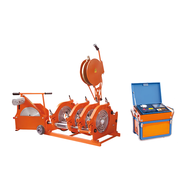
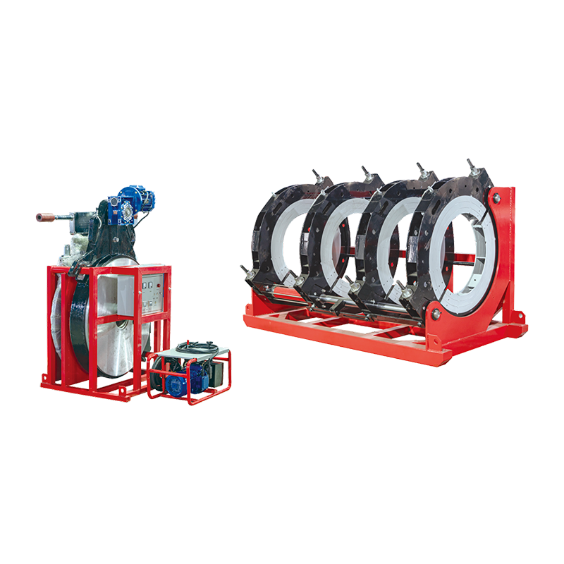
An Automatic Butt Fusion Welding Machine joins two polyethylene pipe ends into a single, monolithic wall by heating the faced surfaces on a controlled heater plate, then pressing them together under a programmed pressure profile while a microprocessor or PLC manages every stage of the cycle without the operator manually driving the hydraulics. The result is a joint that is, in practical terms, as strong as the pipe itself when the parameters are followed correctly.
Unlike a manual or hydraulic-lever machine, where the operator judges pressure by feel and reacts to a stopwatch, an automatic machine executes facing, heat soak, changeover, fusion, and cooling as a single pre-programmed sequence. The operator's role shifts from actively driving each phase to entering the pipe diameter and SDR, confirming alignment, and monitoring the readouts on a screen.
This shift matters more than it sounds. Butt fusion is a time-critical process: once the heater plate is removed, the melted pipe faces begin cooling within seconds, and a delay of even a few seconds on smaller pipe can mean the difference between a sound joint and a weld with reduced strength. A machine that automates timing removes the single largest source of variability in the entire process, which is the operator's own reaction speed and consistency across a long shift.
In practice, the term covers a fairly wide family of equipment, from compact frames for 63 mm service pipe up to heavy hydraulic rigs capable of joining pipe over a meter in diameter. What all of them share is closed-loop control over temperature, pressure, and time, plus, on nearly every modern unit, a built-in data logger that records each weld for later review.
Why Polyethylene Pipe Can Be Fused Rather Than Glued or Bolted
Butt fusion works because polyethylene is a thermoplastic: heating it does not trigger a chemical reaction, it simply softens the material enough for polymer chains near the surface to move freely. When two heated faces are pressed together, chains from each side migrate across the interface and become entangled as the joint cools, so the boundary between the two original pipe ends effectively disappears at a molecular level. This is different from adhesive bonding, where a third material glues two surfaces together, and different from mechanical jointing, where a fitting clamps or compresses the pipe without altering the material itself.
Because the joint is made of the same material as the pipe wall, a correctly fused butt weld does not introduce a new failure point the way a gasket or a threaded connection can. This is the main reason butt fusion is the default jointing method for buried gas and water polyethylene pipe worldwide: there is no seal to age, no bolt torque to lose, and no dissimilar material at the joint that could corrode or degrade at a different rate than the pipe itself.
The trade-off is that fusion quality depends entirely on process control at the moment the joint is made. A bolted flange can be re-torqued and a mechanical fitting can be re-tightened, but once a fusion joint has cooled, any deficiency in temperature, pressure, alignment, or timing is locked into the pipe wall permanently. This is precisely why automatic machines exist: they turn a process that depends on operator skill and attentiveness into one that depends primarily on machine calibration, which is far easier to verify and repeat consistently across hundreds of joints on a single project.
Inside the Automatic Fusion Cycle: Six Stages Explained
Every standard-compliant butt fusion joint, automated or not, passes through the same six physical stages. What changes with automation is how tightly each stage is controlled and logged, and how much of the decision-making is removed from the operator's hands.
-
Clamping and Alignment
The pipe ends are loaded into four (or more, on large-diameter machines) hydraulic clamp inserts sized to the pipe outer diameter. On automatic machines, alignment is checked electronically or against a fixed reference, and the clamps lock the pipe axially true so the facing tool and heater plate meet the ends square. Poor clamping is one of the most common root causes of field failures, because even a well-executed heat and pressure cycle cannot compensate for pipe ends that are not concentric with one another.
On larger frame sizes, the clamps themselves are often precision die-cast and machined on the contact face specifically to avoid distorting the pipe wall under clamping load, since an oval or pinched clamp zone can translate into an out-of-round joint face further down the line.
-
Facing (Trimming)
A rotating planer trims both pipe faces to remove oxidation, scratches, and out-of-square cuts. The machine typically drives the facer under a fixed drag pressure and stops automatically once a continuous, unbroken shaving is produced on both sides, which is the visual signal that the faces are flat and parallel. Facing also removes any surface skin that has already begun to oxidize from exposure to air, since oxidized polyethylene does not fuse as cleanly as freshly exposed material.
Facer blade condition is worth watching closely: a dull or chipped blade produces an interrupted shaving even when the machine records normal drag pressure, so operators are still expected to visually confirm a continuous ribbon of shavings rather than relying on the pressure reading alone.
-
Heating (Bead-Up and Heat Soak)
A PTFE-coated heater plate, held at a set temperature, is inserted between the pipe ends. Bead-up pressure brings the pipe faces into contact with the plate to raise a small melt bead, after which pressure drops to near zero so heat can soak into the wall thickness for a duration calculated from wall thickness and material grade. The bead-up step also compensates for minor out-of-true conditions left over from facing, since the small amount of pressure helps seat both faces evenly against the plate.
Heat soak is the longest single stage in the cycle on thick-walled pipe, and it is the stage where automatic temperature regulation earns its value: a plate that drifts even a few degrees below setpoint during a long soak period under-heats the core of the wall, while a plate that runs hot can degrade the surface material before the pipe ends ever touch.
-
Plate Removal and Changeover
The heater plate is withdrawn and the molten pipe ends are brought together within a strict changeover window, usually only a few seconds for smaller diameters and longer on large pipe. Automatic machines time this step precisely because even a short delay lets the melted surface skin over and cool, producing a cold joint. This is also the stage most prone to human error on manual equipment, since the operator has to physically swing or slide a heavy heater plate out of the way and bring the carriage together fast enough, all while the melt is actively cooling.
-
Fusion (Joining Under Pressure)
The molten ends are pressed together under the specified fusion pressure, forming a double roll-back bead where a visible V-groove stays above the pipe surface. This bead shape is the primary visual indicator that pressure, temperature, and timing were all within tolerance. Pressure is typically ramped up rather than applied instantly, since a sudden pressure spike can push molten material out of the joint area rather than allowing it to fuse evenly across the full wall thickness.
-
Cooling Under Pressure
Pressure is held while the joint cools, typically for a period roughly proportional to wall thickness, so the fused zone solidifies under load rather than relaxing prematurely. Only after this hold period does the machine release the clamps. Releasing pressure too early is a common cause of joints that look acceptable on the outside but carry internal stress concentrations, since the material has not fully re-crystallized under load.

Fusion Parameters That Actually Determine Joint Strength
Three variables control weld quality: heater plate temperature, interfacial pressure, and time. Every recognized procedure sets tolerances for each, and the differences between procedures reflect different national traditions rather than fundamentally different physics. The table below summarizes the ranges used by the main international and regional procedures referenced by pipe fusion equipment worldwide.
| Procedure | Heater Plate Temperature | Fusion / Bead-Up Pressure | Notes |
|---|---|---|---|
| ISO 21307 (SLP method) | 210 to 225 degrees C | 0.17 ± 0.02 MPa initial bead-up | Most widely referenced international procedure for gas and water pipe |
| DVS 2207-1 (Germany) | Around 210 to 230 degrees C | 0.15 N/mm² single low pressure | Near-zero pressure held during heat soak |
| ASTM F2620 (USA) | Manufacturer-specified, commonly near 400 degrees F | 60 to 90 psi interfacial pressure | Single higher interfacial pressure approach |
| GB/T 32434-2015 SLP (China) | 200 to 235 degrees C | 0.15 ± 0.01 MPa dynamic | Wall thickness up to 70 mm |
| GB/T 32434-2015 DLP (China) | 225 to 240 degrees C | 0.15 ± 0.02 MPa fusion, 0.025 ± 0.002 MPa cooling | Dual-pressure profile for thicker walls |
Regardless of which procedure a project follows, heater plate stability is generally expected to stay within about plus or minus 3 degrees C of the setpoint, since a plate that drifts outside this band changes melt depth and directly affects joint strength. This is one of the main reasons automatic machines use closed-loop temperature control rather than a simple on-off thermostat, because a thermostat that merely cycles power on and off tends to overshoot and undershoot the target rather than holding it steady through a long heat soak.
Material Grade Changes the Tolerance Window
PE100 and PE80 pipe are not interchangeable in terms of fusion parameters even though the process looks identical from the outside. PE100 generally tolerates a narrower heat soak window than PE80, commonly cited around 210 degrees C give or take about 5 degrees, and controllers loaded with the wrong material table can produce welds that pass a visual check but carry reduced long-term strength. Polypropylene pipe, which also uses butt fusion in some industrial and chemical process applications, runs at a different temperature band entirely and should never share a parameter table with polyethylene.
Wall Thickness and the SDR Relationship
Standard Dimension Ratio, or SDR, describes the relationship between pipe outer diameter and wall thickness. A lower SDR number means a thicker wall relative to diameter, which in turn means a longer required heat soak time and a longer cooling time, since heat has further to travel to reach the core of the material and the fused zone takes longer to fully solidify under pressure. Automatic controllers store SDR-based tables so the operator only has to select diameter and SDR rather than calculate soak and cooling times manually for every joint.
Machine Architecture: What Sets Automatic Machines Apart
Several subsystems distinguish a fully automatic butt fusion welding machine from a manual or semi-automatic unit, and understanding each one helps explain why automatic equipment costs more up front but reduces variability across a large volume of welds.
Hydraulic Power Unit
A sealed hydraulic station drives clamping, facing, and fusion pressure. On automatic machines this unit is servo-controlled or proportionally valved so pressure ramps and holds match the programmed profile instead of relying on the operator's hand on a lever. A fully enclosed hydraulic station also reduces the risk of the operator being exposed to pressurized fluid during operation.
Programmable Controller
A touchscreen PLC or microprocessor stores pipe diameter and SDR tables, calculates heat soak and cooling times automatically, and sequences the six fusion stages without further operator input once the cycle starts. Most controllers also display a running graph of temperature and pressure so the operator can watch the actual cycle track against the target profile in real time.
Heater Plate and Facing Tool
The heater plate uses a PTFE-coated surface for even heat transfer and a fast recovery time between welds. The facing tool is typically a curved-blade planer designed to produce a chipless, continuous shaving that confirms a flat, parallel joint face. Both components are wear items and are generally designed to be swapped out as the machine ages rather than repaired in place.
Data Logger
Nearly every automatic machine records temperature, pressure, drag force, and timing for each weld to internal memory or a removable card, creating a digital record that can be reviewed or downloaded after the joint is buried or otherwise inaccessible. Some newer units also transmit this data over a mobile network so records can be reviewed from an office in near real time.
Clamp Inserts and Frame
Clamp inserts are sized to specific pipe diameters and are usually die-cast or machined to grip the pipe evenly around its circumference without distorting the wall. The frame itself needs enough structural rigidity to resist bending under full fusion pressure, since a frame that flexes under load introduces exactly the kind of misalignment the clamps are meant to prevent.
Safety Interlocks
Automatic machines commonly include guarding and interlocks around the heater plate and facer, since both components reach temperatures or use cutting action that can injure an operator working close to the pipe. Interlocks typically prevent the facer from running with the heater plate in position, and vice versa, so the two tools cannot physically collide inside the machine.
Manual vs Semi-Automatic vs Fully Automatic: A Practical Comparison
Choosing between machine types usually comes down to project volume, pipe diameter, and how much weld traceability a contract requires. None of the three categories is universally correct, and many contractors keep more than one type in their fleet for different job types.
| Feature | Manual | Semi-Automatic Hydraulic | Fully Automatic |
|---|---|---|---|
| Pressure control | Operator judgement | Hydraulic gauge, manual lever | Closed-loop, pre-programmed |
| Cycle timing | Stopwatch, manual tracking | Manual with timer alerts | Automatic sequencing |
| Data logging | Paper log, if any | Optional add-on logger | Built in as standard |
| Operator training curve | Long, skill-dependent | Moderate | Shorter, but still requires competence in setup and inspection |
| Consistency across many welds | Varies with operator fatigue | More consistent than manual | Highest, since the machine repeats the same profile every time |
| Best suited for | Small diameter, low volume | Mid-size pipe, moderate volume | Municipal, gas, and high-volume infrastructure work |
| Operator dependency | High | Moderate | Low, supervision rather than active control |
The consistency argument is often the deciding factor for larger projects. A single fatigued or rushed changeover on a manual machine can produce a defective joint that looks fine from the outside, and on a long pipeline with hundreds of joints, even a small defect rate translates into a meaningful number of weak welds. Automatic machines do not eliminate operator error entirely, since setup, alignment checks, and visual bead inspection still depend on the person running the machine, but they remove the timing and pressure variability that is hardest for a human to control precisely over a full shift.
Matching Machine Size to Pipe Diameter
Automatic butt fusion welding machines are generally built in frame sizes that correspond to pipe diameter ranges, since clamp bore, heater plate area, and hydraulic tonnage all scale with pipe size. Choosing an undersized machine for a given pipe diameter is not simply inconvenient, it can prevent the machine from generating enough fusion pressure to properly join thick-walled pipe.
| Frame Class | Pipe Diameter Range | Typical Application |
|---|---|---|
| Compact | 63 to 160 mm | Service connections, small distribution lines |
| Mid-size | 160 to 315 mm | Water distribution mains, irrigation |
| Large | 315 to 630 mm | Municipal trunk mains, gas transmission |
| Heavy duty | 630 to 1200 mm and above | Large infrastructure, mining, and marine outfall pipelines |
Larger frame classes generally require a lifting crane or gantry to load pipe into the clamps, since both the pipe sections and the machine itself become too heavy for manual handling once diameters pass roughly 500 mm. On heavy duty frames, the heater plate alone can weigh well over what a single operator should lift unassisted, which is why larger machines often include a powered plate carriage or hoist rather than relying on the operator to swing the plate by hand.
Portability and Site Access
Compact and mid-size frames are generally designed to break down into components that fit through standard trench access or be carried by two people, which matters on service and distribution work where the machine has to move between many joint locations in a single day. Heavy duty frames trade portability for capacity, since a single trunk main project may only require the machine to be set up a handful of times across an entire job, with far fewer but far larger joints than a distribution network.
Common Weld Defects and How Automation Reduces Them
Cold Fusion
Occurs when the changeover time between plate removal and joining runs too long, letting the melted surface cool and skin over before contact. Automatic sequencing enforces the changeover window consistently, which removes the human reaction-time variable that causes most cold joints. Cold fusion is particularly dangerous because the joint can look visually normal from the outside while carrying significantly reduced strength internally.
Misalignment
A joint where the pipe walls do not sit flush produces uneven stress concentration. Precision clamp inserts and electronic alignment checks on automatic machines catch out-of-round or offset pipe before the cycle starts. Misalignment left uncorrected shows up later as an uneven bead, with one side of the V-groove wider or narrower than the other around the circumference.
Insufficient or Uneven Bead
A flat, one-sided, or undersized bead usually points to low pressure, low temperature, or contamination on the pipe face. Automatic pressure and temperature logging make this condition traceable back to the specific weld and cycle stage that caused it, which is far more useful during troubleshooting than a paper log that only records whether a weld happened at all.
Contamination
Dirt, moisture, or grease on the pipe face or heater plate weakens the melt bond. This defect is mechanical rather than electronic, so automation reduces but does not eliminate it; site housekeeping and end-capping pipe against wind-blown dust remain the operator's responsibility regardless of how advanced the machine is.
X-Type or Distorted Bead Profile
Research on welded joints has documented an X-shaped bead cross-section that can appear when pressure and temperature are not properly balanced, and mechanical strength has been shown to decrease as the distance between the two X lines narrows. This is a subtler defect than a flat bead and is one of the reasons destructive sample testing remains valuable even on projects using well-calibrated automatic equipment.
Quality Control and Testing After Welding
A completed joint is inspected in layers, starting with the fastest and least invasive check and moving toward more rigorous testing on critical lines or as spot checks across a project.
Visual Inspection
Every joint should be visually checked for a uniform double roll-back bead running the full circumference, with the V-groove between the two beads staying above the surrounding pipe surface. A flat, concave, or notched bead is a visual sign the weld should be investigated further before the line is put into service.
Destructive Sample Testing
Bend-back and side-bend tests involve cutting a strip across the joint and folding it to check whether the fusion line separates. Tensile and high-speed tensile impact tests pull a sample to failure and record where the break occurs, since a weld that fails through the parent pipe material rather than along the fusion line is generally considered evidence of a sound joint. These tests destroy the sample, so they are used on representative joints rather than every weld on a project.
Non-Destructive Testing
Ultrasonic methods, including phased-array ultrasonic testing, have become the primary non-destructive option for HDPE butt fusion because they can be applied without cutting the pipe open. Because polyethylene has high ultrasonic attenuation and does not support shear waves the way metal does, phased-array systems typically rely on longitudinal waves and specialized wedges to generate usable images of the fused zone. Time-of-flight diffraction and microwave-based methods have also been studied for detecting lack-of-fusion conditions, though ultrasonic and mechanical testing remain the most commonly cited combination in practice.
Hydrostatic Testing
Once a section of pipeline is fully installed, a short-term hydrostatic test at a pressure above normal operating pressure is commonly used to confirm the line, joints included, can hold pressure without leaking before it is put into permanent service.

Data Logging and Weld Traceability in the Field
What gets recorded
Heater temperature, facing drag, bead-up pressure, heat soak time, changeover time, fusion pressure, and cooling time for every individual joint, along with a timestamp and, on many machines, an identifier for the operator and the specific weld number.
Why it matters
Once a joint is buried or the pipeline is pressurized, the weld itself cannot be re-inspected without cutting it out. A digital record is often the only evidence that the procedure was followed correctly, and it is what a project owner or regulator will ask for if a failure investigation ever becomes necessary.
Records are typically stored on internal memory or a removable card and can be transferred to a computer or, on newer machines, sent over a mobile network so a project manager can review welds from an office rather than waiting for site paperwork. On critical lines, sample joints are still validated destructively through bend-back or tensile testing regardless of what the data logger shows, since the log confirms process parameters rather than the finished mechanical strength directly. In other words, a good data log tells you the machine did what it was told to do; it does not, by itself, guarantee that the material fused perfectly, which is why destructive and non-destructive testing remain part of a complete quality program even on fully automated equipment.
Where Automatic Machines Deliver the Biggest Practical Advantage
The case for automation is strongest on projects where weld count is high, diameters are large, or the contract requires documented traceability for every joint. On a small job with a handful of welds, the efficiency gained by automation may not offset the higher purchase or rental cost compared with a semi-automatic machine. On a distribution or transmission project with hundreds of joints, the picture changes considerably.
Labor and Crew Size
Because automatic machines handle timing and pressure internally, crews can often run with fewer people actively engaged in each weld, freeing labor for pipe handling, trench work, or preparing the next joint location while the current cycle completes.
Cycle Repeatability Across a Long Shift
Operator fatigue is a real factor on manual equipment: the tenth weld of a hot afternoon is rarely executed with the same precision as the first. Automatic sequencing performs the two hundredth weld exactly the same way as the first, which matters most on projects where consistency across a large number of joints is the actual deliverable.
Documentation for Owners and Regulators
Gas utilities in particular tend to require documented weld records as a matter of standard practice, since a buried gas line cannot be re-opened for inspection without significant cost and disruption. A built-in data logger turns this requirement from an administrative burden into something the machine produces automatically as a byproduct of doing its job.
Daily Operating and Maintenance Practices That Protect Weld Quality
- Wipe the heater plate clean after every weld and inspect the PTFE coating for scratches that could stick melted material to the plate.
- Verify heater plate temperature against an independent surface probe at the start of each shift, since a built-in display can read differently from the actual plate surface over time.
- Cap open pipe ends before and during heating, since an open pipe acts like a chimney and cools the joint unevenly around the circumference.
- Shield the joint area from wind, rain, and direct sun, since strong sunlight can heat the top of the pipe faster than the bottom and skew fusion results.
- Keep the heater plate in its insulated holster between welds so it does not lose heat while waiting for the next joint.
- Check clamp inserts for wear, since worn inserts allow the pipe to shift slightly under pressure and introduce misalignment.
- Inspect the facing tool blades for chips or dullness before each shift, since a dull blade can produce an interrupted shaving even while the machine reports normal drag pressure.
- Check hydraulic hoses and fittings regularly for leaks or wear, since a slow pressure leak during the fusion or cooling stage can silently reduce the actual joining pressure below the programmed setpoint.
- Keep a record of which pipe batches and diameters were welded with which machine settings, in case a material or dimensional issue is traced back after installation.
- If site conditions differ meaningfully from the conditions the procedure was set up under, pause and re-check parameters rather than continuing on assumption.
Choosing the Right Machine for a Project
Selecting a machine is less about finding the most advanced controller available and more about matching the equipment to the actual demands of the job.
Pipe Diameter Range and SDR
Confirm the machine's rated diameter range and hydraulic tonnage cover the thickest wall pipe expected on the project, not just the largest diameter, since a thick-walled small-diameter pipe can require more fusion pressure than a thin-walled larger pipe.
Site Conditions and Portability
Trench access, available power, and how many separate weld locations the crew needs to reach in a day all influence whether a compact, breakdown-capable frame or a heavier stationary rig makes more sense.
Documentation Requirements
Projects with a gas utility, government, or large institutional owner behind them often specify data logging as a contractual requirement. Confirming the format and detail level of the machine's data log against the project specification before mobilizing avoids discovering a documentation gap after welding is already underway.
Serviceability
Heater plates, facing blades, and clamp inserts are wear items on every machine regardless of brand or automation level. Access to replacement parts and technical support in the region where the machine will actually be used tends to matter more over the life of the equipment than any single feature on the control panel.
Frequently Asked Questions
What pipe diameters can an automatic butt fusion welding machine handle?
Depending on frame size, automatic machines commonly cover everything from around 63 mm service pipe up to large-diameter trunk mains of 1200 mm or more, with clamp inserts and heater plates swapped or sized to match each diameter range.
How is heat soak time calculated?
Heat soak time is generally proportional to wall thickness, since thicker walls need longer for heat to penetrate evenly to the core of the material. Automatic controllers typically calculate this automatically once the operator enters pipe diameter and SDR.
Why does changeover time matter so much?
The molten pipe surface begins cooling the instant the heater plate is withdrawn. If too much time passes before the pipe ends meet, the surface partially solidifies and the two halves cannot fully interlock at the molecular level, producing a cold joint that can fail under stress despite looking normal from the outside.
Can an automatic machine weld both PE80 and PE100 pipe?
Yes, provided the correct parameter set is loaded for the material grade. PE100 generally tolerates a narrower heat soak window than PE80, so the controller's material and diameter tables need to match the pipe actually being welded.
Does automation remove the need for a trained operator?
No. Automation controls the physical variables precisely, but surface preparation, alignment checks, environmental shielding, and interpreting the bead shape after each weld still depend on operator competence and attention.
How can I tell if a completed joint is sound just by looking at it?
A healthy joint shows a uniform double roll-back bead running the full circumference, with the V-groove between the two beads staying above the surrounding pipe surface. A flat, one-sided, or notched bead is a visual sign the weld should be investigated further.
Is destructive testing still necessary if the machine logs every parameter automatically?
Generally yes on critical lines. A data log confirms the machine executed the programmed temperature, pressure, and timing, but it does not directly measure the mechanical strength of the finished joint, so bend-back, tensile, or non-destructive testing on sample welds remains a common part of a complete quality program.
Can polypropylene pipe be joined on the same machine used for polyethylene?
The mechanical process is similar, but polypropylene fuses at a different temperature band than polyethylene, so the controller needs a separate material table and the heater plate temperature must be reset accordingly rather than reused from a polyethylene profile.
Why do some joints show an uneven bead even when the machine reports normal pressure?
An uneven bead despite normal recorded pressure usually points to a mechanical issue upstream of the pressure system itself, such as a worn clamp insert allowing slight pipe movement, an out-of-square facing cut, or contamination on one side of the joint face that the pressure gauge cannot detect.
How often should heater plate temperature be checked against an external reference?
A common field practice is checking at the start of every shift and again if the machine has been idle for an extended period, since a built-in display can drift from the actual plate surface temperature over time, particularly if the temperature sensor itself is exposed to repeated thermal cycling.