 English
 中文简体
中文简体 русский
 عربى
عربى

Content
- 1 1. Core Principle Unveiled: How Does the Machine Achieve "Seamless Union" of Plastic Pipes?
- 2 2. Full Operation Process: What Key Steps Are Required from Preparation to Completion?
- 3 3. Quality Control: How to Ensure the Joint is "As Solid as a Rock"?
- 4 4. Scene Adaptation: How to Deal with Challenges in Different Working Environments?
- 5 5. Common Problems and Solutions: How to Quickly Resolve On-Site Issues?
- 6 6. Equipment Selection Guide: How to Choose the Right Machine for Different Needs?
- 7 7. Daily Maintenance: Extend Service Life with Scientific Upkeep
- 8 8. Safety Operation: Critical Rules for Accident Prevention
1. Core Principle Unveiled: How Does the Machine Achieve "Seamless Union" of Plastic Pipes?
The automatic butt fusion welding machine realizes molecular-level fusion of plastic pipes by precisely controlling the physical properties of thermoplastic materials. Its core principle can be broken down into three dimensions: heat conduction, molecular diffusion, and structural solidification.
In the heat conduction stage, the heating plate releases heat through two methods: resistance heating and electromagnetic induction heating. Resistance heating uses nickel-chromium alloy heating wires with a power density of up to 5W/cm², which can stabilize the temperature between 200-230℃ within 10-15 minutes. Electromagnetic induction heating utilizes alternating magnetic fields to generate eddy currents, with a heating efficiency 20%-30% higher than resistance heating and more uniform temperature distribution, controlling the temperature difference within ±5℃.
The molecular diffusion process requires the coordination of three elements: "temperature-pressure-time". When the heating plate contacts the pipe, the surface temperature of the pipe end quickly rises to the melting temperature. At this point, the initial pressure (usually 0.1-0.3MPa) squeezes out the oxide layer on the pipe end to form a clean melting interface. Subsequently, it switches to low-pressure heat absorption (0.02-0.05MPa) to conduct heat to the interior of the pipe, forming a 1-3mm thick melting layer. During this process, the polyethylene molecular chains gradually unwind, preparing for subsequent diffusion. The "second-level operation" in the switching stage is crucial—if it takes more than 8 seconds, the surface of the melting layer will cool rapidly to form an oxide film, hindering molecular diffusion. Therefore, high-end equipment is equipped with a dual-servo drive system, enabling the heating plate to withdraw at a speed of 0.8m/s and the pipes to dock at a speed of 1.2m/s.
The cooling method in the structural solidification stage directly affects the joint strength. Natural cooling is easy to operate but highly affected by ambient temperature—at -5℃, the cooling time increases by 40%. Forced air cooling uses a high-power fan to generate 3-5m/s airflow, reducing the cooling time by 25%, but excessive wind speed must be avoided to prevent surface cracking of the joint. The water cooling system removes heat through circulating water, offering the highest cooling efficiency and is suitable for large-diameter pipes with a wall thickness exceeding 80mm. However, the water temperature must be controlled between 15-25℃ to avoid thermal stress caused by excessive temperature differences.
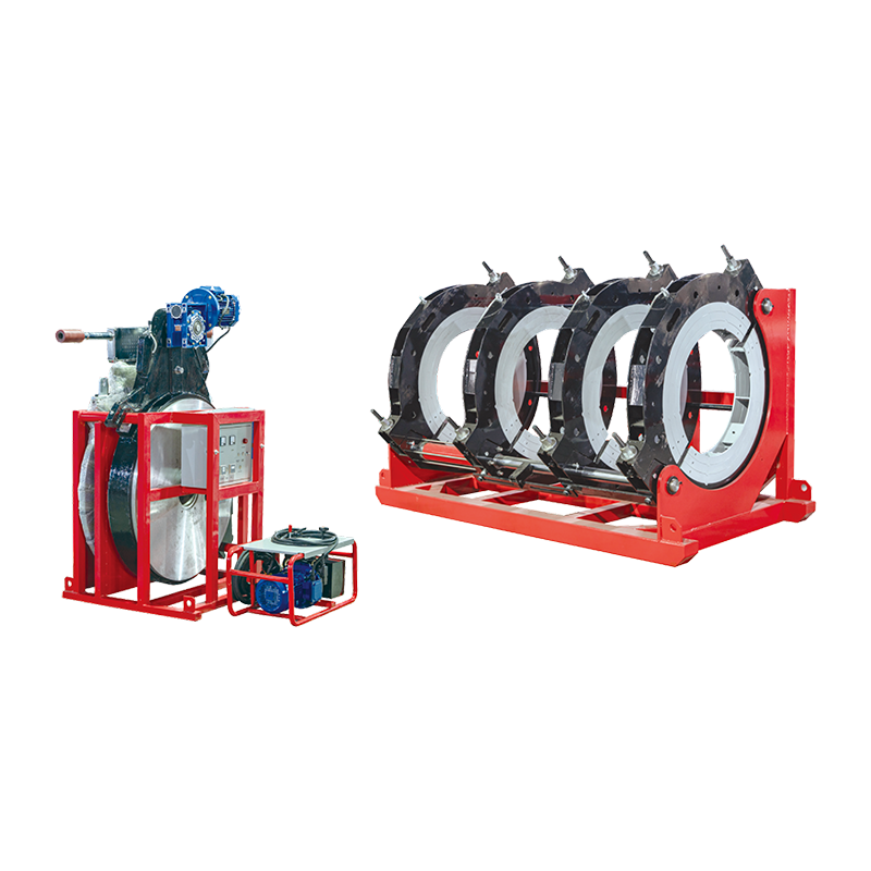
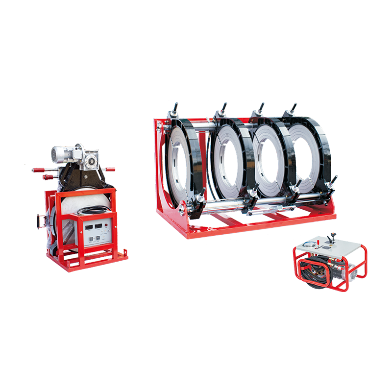
The four core systems supporting this process each have technical highlights: The hydraulic system adopts a variable displacement piston pump with a flow adjustment range of 0-50L/min, which can automatically match the pressure output according to the pipe specifications. For example, it outputs 2.5MPa for 160mm diameter pipes and 8MPa for 630mm diameter pipes. The mechanical structure’s jaws feature an arc design, increasing the contact area with the pipe by 30% to avoid damaging the pipe surface during clamping. Meanwhile, the slide table has a positioning accuracy of ±0.05mm to ensure no misalignment during pipe docking. The control system is equipped with a 32-bit microprocessor with a sampling frequency of up to 100Hz, which can real-time collect parameters such as temperature, pressure, and displacement, and display them in curve form on a 7-inch touch screen for easy operator monitoring. Additionally, it has a data storage function that can save more than 1000 welding records and support export via a USB interface for quality traceability.
2. Full Operation Process: What Key Steps Are Required from Preparation to Completion?
Standardized operation is crucial for ensuring welding quality. The complete process includes three stages: preparation, welding, and cooling, each with strict technical standards and operational points.
In the preparation stage, the first step is to check the matching of equipment and pipes: Select the corresponding jaws according to the outer diameter of the pipe, ensuring the clamping range of the jaws matches the pipe specifications. For example, 90-110mm diameter pipes require 90-110mm jaws—oversized or undersized jaws will cause unstable clamping and displacement during welding. Meanwhile, check the pipe material and wall thickness, as the welding temperature and pressure parameters vary significantly among PE, PPR, and PVC pipes. The welding temperature for PE pipes is usually 200-220℃, 260-280℃ for PPR pipes, and 180-200℃ for PVC pipes—equipment parameters must be adjusted according to the material. Then, use a level to adjust the equipment workbench, ensuring the levelness error of the platform does not exceed 0.1mm/m, and adjust the pipe height with supports to align the pipe axis with the equipment frame centerline, controlling the deviation within 0.5mm. Excessive axis deviation will cause uneven thickening on one side during welding, affecting joint strength.
Pipe pretreatment before welding is equally important: Cut the pipe with a special pipe cutter, ensuring the perpendicularity error between the cutting surface and the pipe axis is less than 0.5°—if the perpendicularity is not up to standard, re-cutting is required. Then, sand the pipe surface to remove the oxide layer, with a sanding range of 20-30mm at the pipe end. After sanding, wipe the surface with a clean cotton cloth and clean the pipe end of oil and impurities with alcohol with a concentration of over 95% to prevent impurities from entering the melting layer and affecting the fusion effect. In addition, check the surface of the heating plate—if there are scratches or oil stains, polish it smooth with fine sandpaper and clean it with alcohol. The flatness error of the heating plate surface must be controlled within 0.03mm/m; otherwise, uneven heating of the pipe will occur.
During formal welding, the milling process is key to ensuring the flatness of the pipe end: Install the milling cutter on the equipment, start the milling cutter motor, and after the milling cutter reaches a stable speed (usually 1400-1800r/min), slowly close the pipes to make the pipe end contact the milling cutter. Apply a pressure of 0.1-0.2MPa until continuous and uniform chips are produced. The chip thickness depends on the pipe wall thickness—0.5-1mm for 5-10mm wall thickness and 1-2mm for 10-20mm wall thickness. If the chips are discontinuous or powdery, the milling cutter is severely worn and must be replaced. After milling, turn off the milling cutter motor and separate the pipes only after the milling cutter stops rotating to avoid scratches on the pipe end.
Docking accuracy inspection is the final check before welding: Close the pipes and use a feeler gauge to check the pipe end gap. The gap standards vary by pipe diameter—no more than 0.3mm for pipes with diameter ≤110mm, 0.5mm for 160-250mm, and 1mm for 315-630mm. Meanwhile, check the pipe misalignment, which must be controlled within 10% of the pipe wall thickness. For example, for a pipe with 10mm wall thickness, the misalignment should not exceed 1mm. If the gap or misalignment exceeds the standard, re-adjust the pipe position or perform milling again.
The heating stage requires strict control of pressure and time: First, apply initial pressure to press the pipe against the heating plate, making the pipe end melt and form a bead. The bead height must meet the standard—1.5mm for 7-12mm wall thickness, 2mm for 12-20mm, and 2.5mm for 20-30mm. After the bead is formed, maintain the initial pressure for 3-5 seconds to ensure the full formation of the melting layer. Then, switch to low-pressure heat absorption, reducing the pressure to 0.02-0.05MPa. The heat absorption time is calculated based on the pipe wall thickness using the formula: Heat absorption time = 10 × wall thickness (seconds). For example, a pipe with 10mm wall thickness requires 100 seconds of heat absorption. During heat absorption, closely observe the bead—if the bead becomes abnormally thick or thin, adjust the pressure in a timely manner.
The switching stage is a critical node in the welding process, requiring the withdrawal of the heating plate and pipe docking to be completed within 5 seconds: First, quickly open the equipment frame and withdraw the heating plate from between the pipes, avoiding contact between the heating plate and the molten end of the pipe. Then, quickly close the pipes and apply full welding pressure. The welding pressure varies by pipe specification—1.8MPa for 90mm diameter, 2.5MPa for 160mm, 3.5MPa for 315mm, and 8MPa for 630mm. After applying the pressure, maintain stability to avoid pressure fluctuations affecting joint quality.
The cooling stage is carried out under pressure preservation, with the cooling time depending on the pipe wall thickness and ambient temperature: For 5-10mm wall thickness, the cooling time is 20-30 minutes at 20℃; 30-50 minutes for 10-20mm; 50-70 minutes for 20-30mm; 70-100 minutes for 30-50mm; and 100-130 minutes for 50-70mm. During cooling, do not touch the pipe or equipment to avoid external forces affecting joint solidification, and maintain good ventilation to prevent heat accumulation from prolonging cooling time.
3. Quality Control: How to Ensure the Joint is "As Solid as a Rock"?
Joint quality is the core of the safe operation of the pipeline system. A comprehensive quality control system must be established from three dimensions: parameter setting, process monitoring, and post-inspection, with clear technical standards and operating specifications for each link.
Precision in Parameter Setting
Parameters must be adjusted according to the pipe material, specification, wall thickness, and ambient temperature, as different parameters have varying impacts on joint quality.
Temperature Parameters
The heating temperature is determined by the pipe material: 200-210℃ for PE80 pipes, 210-220℃ for PE100, 260-270℃ for PPR, 270-280℃ for PPR steady-state pipes, 180-190℃ for PVC-U, and 190-200℃ for PVC-C. Excessively high temperatures cause over-melting and carbonization of the pipe, reducing joint strength; excessively low temperatures fail to form a sufficiently thick melting layer, leading to weak joints. Ambient temperature also affects the heating temperature—at temperatures below 0℃, increase the heating temperature by 5-10℃ to compensate for heat loss; at temperatures above 30℃, reduce it by 3-5℃ to avoid overheating.
Pressure Parameters
Welding pressure is divided into three stages: initial pressure, heat absorption pressure, and welding pressure, with settings adjusted according to pipe specifications. The initial pressure squeezes out the oxide layer on the pipe end to form a clean melting interface, usually 0.1-0.3MPa (higher for larger diameters). The heat absorption pressure maintains contact between the pipe and the heating plate to ensure sufficient heat conduction, usually 0.02-0.05MPa (excessively high pressure thins the melting layer, while excessively low pressure leads to insufficient heat conduction). The welding pressure promotes molecular diffusion in the melting layer to form a strong joint—1.8MPa for 90mm diameter, 2.5MPa for 160mm, 3.2MPa for 250mm, 3.8MPa for 315mm, 4.5MPa for 400mm, 5.5MPa for 500mm, and 8MPa for 630mm. The welding pressure must match the pipe wall thickness—for each 1mm increase in wall thickness, the pressure can be increased by 0.05-0.1MPa, but excessive pressure must be avoided to prevent pipe deformation or joint cracking.
Time Parameters
Time parameters include heating time, heat absorption time, switching time, and cooling time, all of which require strict control. The heating time is calculated as 5 × wall thickness (seconds) — for example, 50 seconds for 10mm wall thickness. The heat absorption time is 10 × wall thickness (seconds) — 100 seconds for 10mm wall thickness. The switching time must be controlled within 5 seconds to ensure the melting layer is docked before cooling. The cooling time depends on the wall thickness and ambient temperature: 20-30 minutes for 5-10mm at 20℃, 30-50 minutes for 10-20mm, 50-70 minutes for 20-30mm, 70-100 minutes for 30-50mm, 100-130 minutes for 50-70mm, and 130-180 minutes for wall thickness exceeding 70mm. In low-temperature environments, extend the cooling time by 20%-30%; in high-temperature environments, reduce it by 10%-15%, but ensure the joint is fully solidified.
Refinement in Process Monitoring
Process monitoring must cover the entire welding process, with real-time anomaly detection to ensure parameter stability.
Real-Time Parameter Monitoring
Leverage the equipment control system’s real-time monitoring function to track changes in temperature, pressure, and time throughout the process. Temperature monitoring ensures the heating plate temperature fluctuates within ±5℃—if the deviation exceeds 10℃, the equipment automatically alarms and pauses welding. Pressure monitoring focuses on the stability of the pressure curve, controlling fluctuations within ±0.1MPa—if there is a sudden rise or drop, immediately check the hydraulic system or pipeline connections. Time monitoring records the actual duration of each stage, with deviations from the set time not exceeding 5%—if the deviation is excessive, adjust the equipment operation speed or parameter settings.
Real-Time Visual Observation
During welding, closely observe the appearance changes of the pipe and joint. In the heating stage, check the bead formation— it should be uniform, continuous, and free of obvious wrinkles or gaps, with a height meeting the standard. In the switching stage, observe the continuity of heating plate withdrawal and pipe docking to avoid impurity mixing caused by contact between the heating plate and the molten end. In the cooling stage, check for deformation, cracks, or shrinkage holes in the joint—if anomalies are found, stop cooling and analyze the cause promptly.
Equipment Status Inspection
Regularly check the equipment operation status: Before welding, inspect the flatness of the heating plate surface, sharpness of the milling cutter, and clamping force of the jaws. During welding, check the motor operation sound, hydraulic system leakage, and normal display of the control system. After welding 5-10 joints, stop the machine to check the accuracy of the heating plate temperature sensor and pressure sensor, ensuring the equipment is in good working condition.
Strictness in Post-Inspection
Post-inspection is the final line of defense for joint quality, requiring multiple inspection methods to ensure compliance with safety standards.
Visual Inspection
100% of all joints undergo visual inspection, focusing on the following: The joint surface should be flat and smooth, free of cracks, depressions, bubbles, or impurities. The bead should be uniformly symmetrical, with height and width meeting standards (height deviation ±0.5mm, width deviation ±1mm). The joint axis deviation must be within 10% of the pipe wall thickness—for example, ≤1mm for 10mm wall thickness. The pipe end cut should be flat, free of burrs or serrated edges. If defects are found during visual inspection, mark the location and conduct further testing.
Dimensional Inspection
Use specialized measuring tools for precise joint dimension measurement. Measure the bead height and width with a vernier caliper—bead height is 1.5mm for 7-12mm wall thickness, 2mm for 12-20mm, and 2.5mm for 20-30mm; bead width is usually 1-1.5 times the wall thickness. Measure the joint length with a straightedge— it should match the pipe wall thickness, generally 2-3 times the wall thickness. Measure the joint roundness with a roundness meter, controlling the error within 1% of the pipe diameter—for example, ≤3.15mm for 315mm diameter. Joints with unqualified dimensions must be re-welded.
Pressure Testing
Pressure testing includes water pressure testing and air pressure testing, with the method selected according to the pipeline application. For water pressure testing, seal both ends of the pipe, inject clean water, and slowly increase the pressure to 1.5 times the design pressure, maintaining it for 30-60 minutes. During this period, observe the pressure gauge reading—if the pressure drop does not exceed 0.05MPa and there is no leakage or deformation of the joint, the sealing performance is satisfactory. For air pressure testing, inject compressed air into the pipe, increase the pressure to 1.2 times the design pressure, and maintain it for 20-30 minutes. Apply soapy water to the joint surface—if no bubbles appear, the joint is leak-free. Pressure testing must be conducted after the joint is fully cooled, and sudden pressure increases must be avoided to prevent pipe damage.
Destructive Testing
3% of joints are randomly selected for destructive testing, including tensile, bending, and impact tests. For the tensile test, fix the joint sample on a tensile testing machine and apply tension at a speed of 5-10mm/min until the sample breaks. If the fracture occurs outside the joint area and the tensile strength reaches over 90% of the base material, the joint is qualified. For the bending test, fix one end of the sample and apply a bending moment at the other end to bend the sample to 90° within 10-15 seconds. If no cracks appear at the joint, it meets the requirements. The impact test uses a pendulum impact testing machine to apply impact force to the joint at a speed of 3.5m/s. For PE pipes, the impact absorption energy should not be less than 5kJ/m² at -20℃; for PPR pipes, it should not be less than 3kJ/m² at 0℃. Destructive testing results must be recorded in detail, and if unqualified joints are found, the cause must be analyzed, and the welding parameters adjusted before re-welding.
4. Scene Adaptation: How to Deal with Challenges in Different Working Environments?
Automatic butt fusion welding machines are widely used in water supply, gas transmission, drainage, and industrial pipeline projects, each with unique environmental challenges that require targeted solutions.
1. Low-Temperature Environment (Below 0℃)
Low temperatures significantly affect welding quality—pipe brittleness increases, heating plate heat loss accelerates, and cooling time prolongs. The following measures must be taken: Preheat the pipes before welding—use a hot air blower to heat the pipe ends (temperature 40-60℃) for 10-15 minutes, avoiding direct heating of the pipe surface to prevent local overheating. Increase the heating temperature by 5-10℃—for example, set PE100 pipe heating temperature to 220-230℃ instead of the standard 210-220℃. Extend the heat absorption time by 20%-30% to ensure sufficient heat conduction to the pipe interior. Use a thermal insulation cover during cooling—cover the joint with a thermal insulation blanket (thermal conductivity ≤0.04W/(m·K)) to slow down heat loss, reducing the cooling time extension by 50%. In addition, the hydraulic oil must be replaced with low-temperature resistant oil (viscosity grade 32#) to prevent the hydraulic system from jamming due to increased oil viscosity.
2. High-Temperature Environment (Above 35℃)
High temperatures cause the pipe surface to soften easily, increasing the risk of deformation during clamping and welding. Countermeasures include: Shade the operation area—set up a sunshade awning to avoid direct sunlight on the equipment and pipes, reducing the pipe surface temperature by 8-12℃. Reduce the heating temperature by 3-5℃—for PPR pipes, lower the heating temperature from 260-270℃ to 255-265℃ to prevent over-melting. Shorten the heat absorption time by 10%-15% to avoid excessive heat accumulation. Use forced air cooling during cooling—install a high-power fan (airflow 5-8m³/min) to blow air around the joint, accelerating heat dissipation. At the same time, the equipment control system must be checked more frequently, as high temperatures may cause unstable sensor performance—calibrate the temperature sensor every 2-3 hours to ensure accurate temperature detection.
3. Humid Environment (Relative Humidity Above 85%)
High humidity increases the risk of electrical component leakage and pipe end oxidation. Protective measures include: Strengthen electrical insulation protection—wrap the equipment power cord and control wire joints with waterproof tape, and install a waterproof cover for the control panel (protection level IP65) to prevent moisture from entering. Dry the pipe ends before welding—wipe the pipe ends with a dry cotton cloth, then use a hot air blower (temperature 50-60℃) to dry for 5-8 minutes to remove surface moisture, avoiding water vapor entering the melting layer to form bubbles. Use anti-oxidation flux—apply a thin layer of flux (such as silicone-based anti-oxidant) to the pipe end before heating to slow down oxidation. After welding, the joint must be checked more carefully for bubbles or gaps, and if any are found, the joint must be re-welded.
4. Narrow Space (Such as Indoor Pipelines, Tunnels)
Narrow spaces limit equipment movement and operator operation, requiring special adaptations: Use small and medium-sized equipment—select equipment with a width of ≤1.2m and a height of ≤1.5m, such as portable automatic welding machines (weight ≤300kg), which can be moved in spaces with a width of 1.5m. Adopt a split structure—separate the control system from the welding host, connecting them with a 5-8m long cable, allowing the operator to control the equipment outside the narrow space. Use a wireless remote control—equipped with a wireless remote control (effective distance ≥10m) to realize remote operation of key steps such as heating, pressure application, and cooling, avoiding the operator working in a confined space for a long time. In addition, strengthen ventilation in the narrow space—install an exhaust fan (air exchange rate ≥6 times/hour) to remove harmful gases generated during welding and ensure good air quality.
5. Common Problems and Solutions: How to Quickly Resolve On-Site Issues?
During on-site operation, various unexpected problems may occur. Timely and accurate solutions are essential to ensure construction progress and quality.
|
Problem Phenomenon |
Possible Causes |
Troubleshooting Steps |
Preventive Measures |
|
Pipe deformation during clamping |
1. Excessive clamping force2. Uneven jaw force distribution3. High pipe surface temperature |
1. Reduce clamping pressure to 1.0-1.2MPa2. Adjust jaw parallelism (deviation ≤0.1mm)3. Cool pipe to room temperature before clamping |
1. Calibrate jaw pressure monthly2. Check jaw alignment before daily use3. Avoid direct sunlight on pipes |
|
Uneven bead formation |
1. Uneven heating plate temperature2. Pipe axis misalignment3. Unstable welding pressure |
1. Replace heating plate if temperature difference >±5℃2. Align axes with laser aligner (deviation ≤0.5mm)3. Repair hydraulic leaks or calibrate pressure sensor |
1. Test heating plate temperature weekly2. Use feeler gauge to check pipe gap before welding3. Inspect hydraulic system daily |
|
Joint leakage during pressure test |
1. Insufficient melting (low temperature/short time)2. Oxide film on pipe end3. Joint cracks |
1. Re-weld with temperature +5-10℃ or time +15%-20%2. Re-sand and clean pipe ends3. Cut off cracked joint and re-weld |
1. Verify parameters before welding2. Clean pipe ends immediately after sanding3. Avoid external force during cooling |
|
Equipment sudden shutdown |
1. Power outage/loose connection2. Overheating protection activation3. Hydraulic overpressure |
1. Check power supply and re-tighten connections2. Cool equipment to <50℃ and reset3. Release pressure manually and inspect valves/pipelines |
1. Use a voltage stabilizer2. Clean cooling system weekly3. Monitor pressure curve in real time |
6. Equipment Selection Guide: How to Choose the Right Machine for Different Needs?
Selecting the appropriate automatic butt fusion welding machine is crucial for ensuring construction efficiency and quality. The selection must consider pipe specifications, project scale, and working environment.
1. Based on Pipe Diameter and Wall Thickness
Small-diameter pipes (≤160mm): Choose a small-sized machine with a clamping range of 20-160mm, such as a portable welding machine (weight 200-300kg) with a single hydraulic cylinder drive, suitable for small-scale projects such as indoor water supply pipelines.
Medium-diameter pipes (200-450mm): Select a medium-sized machine with a clamping range of 63-450mm, equipped with a dual hydraulic cylinder drive system for stable pressure output, suitable for urban water supply and drainage projects.
Large-diameter pipes (≥500mm): Use a large-sized machine with a clamping range of 110-630mm or more, featuring a multi-cylinder synchronous drive system and a high-power heating plate (power ≥15kW) to meet the welding needs of large-diameter, thick-walled pipes in long-distance pipeline projects.
2. Based on Project Scale and Efficiency Requirements
Small-scale projects (daily welding ≤50 joints): Choose an entry-level machine with basic functions, such as a manual parameter setting system and natural cooling, which is cost-effective and easy to operate.
Medium-scale projects (daily welding 50-150 joints): Select a mid-range machine with automatic parameter setting and forced air cooling, equipped with a data storage function for quality traceability, improving work efficiency by 30% compared to entry-level machines.
Large-scale projects (daily welding ≥150 joints): Use a high-end machine with intelligent control, such as an AI-based parameter optimization system and water cooling, supporting 5G data transmission for remote monitoring, and capable of continuous operation for 8-10 hours, significantly improving construction efficiency.
3. Based on Working Environment
Outdoor mobile operations: Choose a machine with good mobility, such as a trailer-mounted welding machine (equipped with a traction device) or a skid-mounted machine (easy to load and unload), and with a high protection level (IP65) to adapt to harsh outdoor environments.
Indoor fixed operations: Select a compact machine with a small footprint (length × width × height ≤2m ×1.2m ×1.5m) and low noise (operation noise ≤75dB) to avoid affecting the surrounding environment.
Special environment operations: For low-temperature environments, choose a machine with a low-temperature resistant hydraulic system and thermal insulation function; for humid environments, select a machine with enhanced waterproof and anti-corrosion treatment (such as galvanized + paint coating on the frame).
When selecting equipment, it is also necessary to consider after-sales service—choose manufacturers with a sound after-sales network, providing timely maintenance and spare parts supply (spare parts delivery time ≤48 hours), to avoid prolonged project delays due to equipment failures. At the same time, the equipment should comply with international standards (such as ISO 12176, ASTM D3261) to ensure compatibility with pipes of different brands and meet the quality requirements of global projects.
7. Daily Maintenance: Extend Service Life with Scientific Upkeep
Scientific daily maintenance is the key to reducing equipment failure rates and extending service life. The following table details the maintenance content and standards for different cycles:
|
Maintenance Cycle |
Maintenance Component |
Maintenance Content |
Qualification Standards |
Tools Required |
|
Daily |
Workbench & Jaws |
1. Clean debris and oil2. Check jaw clamping tightness3. Inspect jaw pad wear |
1. No residual debris2. No pipe slippage during clamping3. Pad thickness ≥80% of original |
Brush, rag, feeler gauge |
|
Daily |
Heating Plate |
1. Wipe surface with alcohol2. Check for scratches/carbonization3. Test temperature uniformity |
1. No oil/stains2. Scratches ≤0.2mm deep3. Temperature difference ≤±5℃ |
Alcohol, infrared thermometer |
|
Daily |
Hydraulic System |
1. Check oil level2. Inspect for leaks3. Test pressure stability |
1. Oil level between "MIN" and "MAX"2. No leakage at joints3. Pressure fluctuation ≤±0.1MPa |
Oil level gauge, pressure gauge |
|
Weekly |
Electrical System |
1. Tighten terminal screws2. Check wire insulation3. Test emergency stop function |
1. No loose terminals2. No insulation cracking3. Emergency stop responds within 0.5s |
Screwdriver, multimeter |
|
Weekly |
Milling Cutter |
1. Sharpen blunt edges2. Check for cracks3. Tighten fixing bolts |
1. Cutter edge is sharp (no burrs)2. No cracks on blade3. Bolts torque meets standard |
Grinding wheel, torque wrench |
|
Monthly |
Slide Rail |
1. Clean rail surface2. Apply lubricating grease3. Check rail straightness |
1. No dust/impurities2. Grease layer uniform (0.1-0.2mm)3. Straightness deviation ≤0.1mm/m |
Rag, grease gun, straightedge |
|
Quarterly |
Hydraulic Oil Replacement |
1. Drain old oil2. Clean oil tank3. Add new oil (same brand/model) |
1. No residual old oil2. Tank interior is clean3. Oil level meets requirement |
Oil drain pan, filter, funnel |
Common Maintenance Misconceptions to Avoid
Over-lubrication: Excessive grease on the slide rail or jaws attracts dust, forming abrasive mixtures that accelerate wear. Apply only a thin, uniform layer.
Ignoring Heating Plate Scratches: Even small scratches cause uneven heat transfer—polish scratches promptly with 400-600 mesh sandpaper.
Delaying Oil Replacement: Hydraulic oil degrades after 6 months (even if not black). Replace oil on schedule to prevent hydraulic pump damage.
Skipping Electrical Inspections: Loose terminals or cracked insulation can cause short circuits. Tighten terminals and check insulation weekly.
8. Safety Operation: Critical Rules for Accident Prevention
Safety is the top priority in on-site operations. Operators must strictly follow the following rules to avoid injuries or equipment damage:
1. Pre-Operation Safety Check
Verify that all protective devices (such as emergency stop buttons, insulation covers) are intact and functional.
Confirm that the equipment is grounded properly (ground resistance ≤4Ω) to prevent electric shock.
Inspect personal protective equipment (PPE): High-temperature-resistant gloves (heat resistance ≥300℃), anti-impact goggles, anti-slip work shoes, and earplugs (for milling operations) must be worn correctly.
2. In-Operation Safety Rules
Do not touch the heating plate or molten pipe end with bare hands—use a dedicated tool to adjust the pipe position.
Keep the operation area clean and free of flammable materials (such as gasoline, alcohol) to prevent fires.
During milling, stand on the side of the milling cutter (not directly in front) to avoid being hit by flying scraps.
Do not disassemble or adjust components (such as the pressure valve, temperature sensor) while the equipment is running.
3. Post-Operation Safety Measures
Turn off the power supply and close the oil circuit valve after operation.
Clean the equipment and arrange tools neatly—do not leave debris on the workbench.
Record equipment operation status and any abnormalities in the maintenance log for follow-up tracking.
In case of accidents (such as burns, electric shock), stop the equipment immediately, provide first aid, and report to the supervisor.