 English
 中文简体
中文简体 русский
 عربى
عربى

Content
- 1 The 5 Basic Joint Types for Fusion Welding
- 2 Butt Joint — The Foundation of Butt Fusion Welding
- 3 T-Joint (Tee Joint) — Branching and Structural Connections
- 4 Corner Joint — Enclosures, Tanks, and Fabricated Structures
- 5 Lap Joint — Overlapping Members and Thin Material Applications
- 6 Edge Joint — Thin Plate and Sheet Metal Fusion
- 7 Comparison of the 5 Joint Types: Strengths, Weaknesses, and Typical Applications
- 8 How Joint Type Selection Affects Butt Fusion Welding Machine Choices
- 9 Joint Preparation: The Step That Determines Weld Quality Before the Machine Starts
- 10 Weld Bead Inspection: Reading the Butt Joint After Fusion
- 11 Standards and Certifications That Govern Butt Fusion Welding
- 12 Common Defects in Butt Fusion Joints and How to Prevent Them
- 13 Frequently Asked Questions
- 13.1 Which of the 5 joint types is strongest in fusion welding?
- 13.2 Can a butt fusion welding machine weld all 5 joint types?
- 13.3 What diameter range do butt fusion welding machines typically cover?
- 13.4 Is a lap joint ever used in pipe fusion welding?
- 13.5 How long does a butt fusion weld take to cool before the joint can be stressed?
The 5 Basic Joint Types for Fusion Welding
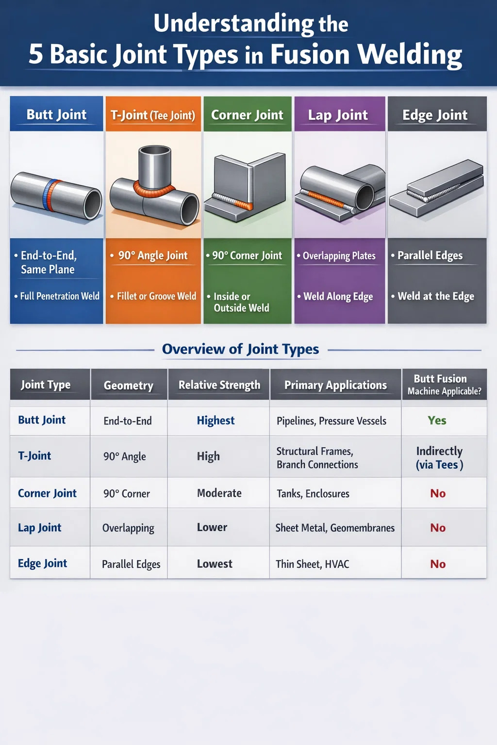
The five basic joint types used in fusion welding are: butt joint, T-joint (tee joint), corner joint, lap joint, and edge joint. Each serves a distinct structural purpose and determines how two pieces of base material are positioned and joined. Selecting the wrong joint type leads to stress concentration, weak welds, and premature failure — especially in pressure-rated piping systems where Butt Fusion Welding Machines are standard equipment. Understanding when and why to use each joint is not a theoretical exercise; it directly affects leak tightness, load-bearing capacity, and service life.
In thermoplastic piping — HDPE, PP-R, and PVDF systems — joint type selection is closely tied to equipment choice. A butt fusion welding machine, for instance, is engineered specifically for butt joints on pipe ends, and using it for any other geometry requires special tooling or is simply not applicable. Knowing the boundaries of each joint type helps engineers and field crews make better decisions before a single bead is laid.
Butt Joint — The Foundation of Butt Fusion Welding
A butt joint places two pieces of material end-to-end on the same plane. It is the most widely used joint configuration in pipeline construction and pressure vessel fabrication because the weld path runs straight through the cross-section of both parts, allowing full-penetration fusion. When properly executed, a butt joint achieves near-parent-metal strength and distributes load evenly across the entire weld zone.
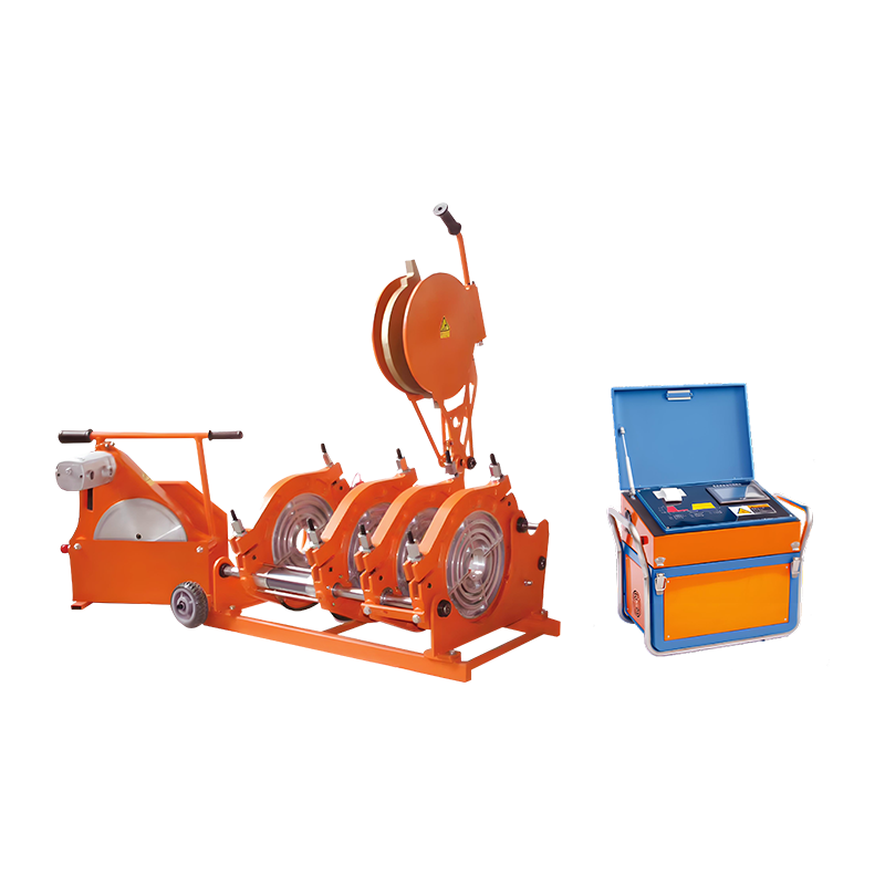
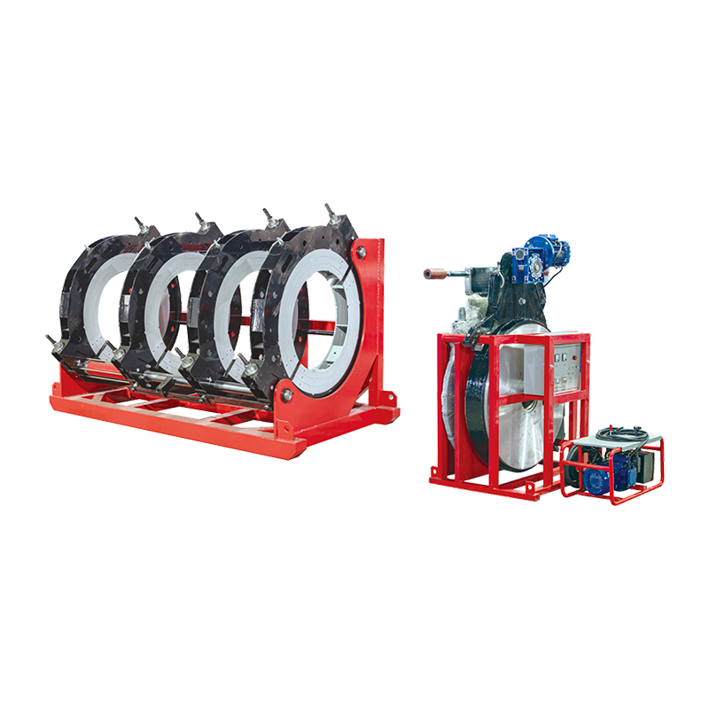
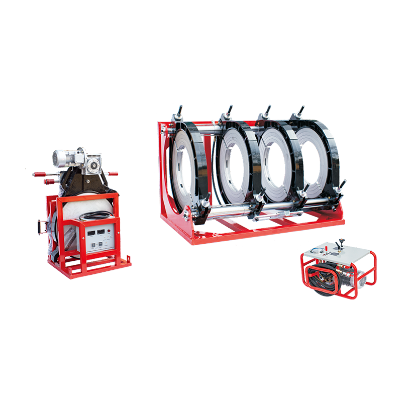
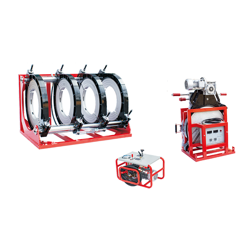
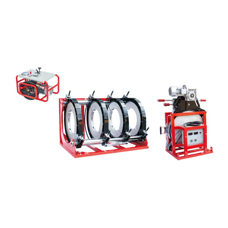
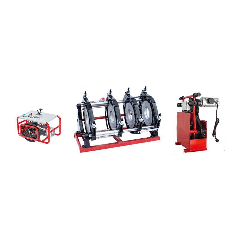
This is precisely the geometry that butt fusion welding machines are built to handle. The machine clamps both pipe or fitting ends in aligned fixtures, faces the mating surfaces with a rotating trimmer to create perfectly flat and parallel contact faces, heats both surfaces simultaneously against a calibrated heating plate, then withdraws the plate and applies controlled fusion pressure to form the joint. The result is a continuous, homogeneous weld across 100% of the pipe wall thickness.
Why Butt Joints Dominate Thermoplastic Pipe Systems
For HDPE pipe networks operating at pressures from 4 bar up to 25 bar, the butt joint is almost universally preferred. Studies on HDPE pipe welds consistently show tensile strength at or above 95% of the base material rating when butt fusion procedures follow ISO 21307 or ASTM F2620 protocols. The joint introduces no angular stress risers and maintains the pipe's full internal bore, which is critical for flow efficiency in water distribution, gas transmission, and industrial fluid handling.
Butt fusion welding machines are available across a wide diameter range — compact hydraulic units handling pipes from DN 63 mm up to large-frame machines processing DN 1600 mm and beyond. CNC-controlled variants log heater plate temperature, fusion pressure, and dwell time automatically, creating digital traceability records that meet ISO 12176-4 data logging requirements for critical infrastructure projects.
Key Parameters That Determine Butt Joint Quality
- Heater plate temperature: typically 200–230°C for HDPE, verified with a calibrated contact thermometer before each weld cycle
- Heating time: calculated based on pipe wall thickness (SDR), usually between 40 and 210 seconds for wall thicknesses from 4 mm to 60 mm
- Changeover time: the interval between plate removal and joint closure must be kept below specified limits — typically 4–6 seconds for most HDPE grades
- Fusion pressure: calculated from pipe outside diameter and wall thickness, not guessed — pressure gauges on the butt fusion welding machine must be verified against traceable standards
- Cooling time under pressure: premature release creates weak, spongy welds; minimum cooling durations are specified per material and wall thickness in welding procedure standards
Misalignment is another variable the machine must control. HDPE pipe roundness tolerance means ends rarely match perfectly. Good butt fusion welding machines include hydraulic alignment clamps that correct ovality and angular deviation, holding mismatch below the 10% of wall thickness limit specified by DVS 2207-1 and similar standards.
T-Joint (Tee Joint) — Branching and Structural Connections
A T-joint, also called a tee joint, is formed when one piece of material meets another at a 90° angle, creating a cross-section that resembles the letter T. One member is the web (the upright), and the other is the flange (the base). This configuration is extremely common in structural steel fabrication, shipbuilding, pressure vessel nozzle attachment, and piping branch connections.
In metal fusion welding — MIG, TIG, and submerged arc welding — T-joints are welded with fillet welds along both sides of the web, or with partial/full penetration groove welds when higher strength and fatigue resistance are required. A double-sided fillet weld on a T-joint with a leg length equal to 0.7 times the plate thickness typically provides adequate strength for static loads, but dynamic or cyclic loading demands full penetration and careful root inspection.
T-Joints in Thermoplastic Systems
In HDPE and polypropylene piping, true T-joints between pipes are not created by direct fusion welding in the field in the same way as metal. Instead, prefabricated tee fittings with butt fusion ends are inserted into the line, and the branch connection is formed by two butt joints — one on each side of the fitting. This means butt fusion welding machines are still the tool of choice even for branching pipelines, because the geometry problem is solved at the fitting design stage, not at the welding stage.
Electrofusion saddle fittings offer an alternative approach for creating branch connections without cutting the main pipe — a cutter inside the fitting is activated after fusion to open the flow path. This method is commonly used for gas service connections where pressure cannot be interrupted.
Corner Joint — Enclosures, Tanks, and Fabricated Structures
A corner joint connects two pieces of material at their edges, forming a 90° corner — like the corner of a box or a rectangular frame. The weld is placed either on the inside face (closed corner joint), outside face (open corner joint), or both, depending on the loading conditions and accessibility requirements.
Corner joints are prevalent in the fabrication of tanks, enclosures, structural frames, and sheet metal assemblies. For pressure-retaining applications, an open corner joint with full root penetration is usually required, which demands careful joint preparation and tight fit-up control. The risk with corner joints is incomplete fusion at the root, which creates a notch that concentrates stress under cyclic loading.
In thermoplastic tank fabrication — polyethylene and polypropylene chemical storage vessels — corner welds are produced by hot gas welding or extrusion welding rather than butt fusion. The flexibility and small torch diameter of hot gas equipment allows work in confined corners, while extrusion welding deposits a continuous bead of filler material in a single pass, reducing multi-pass labor and improving weld consistency in thicker plate sections.
Lap Joint — Overlapping Members and Thin Material Applications
A lap joint is formed by overlapping two pieces of material and welding along the exposed edge of one or both. The joint introduces a natural eccentricity — the load path is not straight — which creates bending moments and stress concentrations at the weld toes. For this reason, lap joints are generally avoided in primary structural members and pressure systems, but they are widely used in sheet metal work, automotive body panels, and applications where one-sided access limits other options.
The strength of a lap joint depends heavily on the overlap length. A common rule in structural design is to make the overlap at least four times the thickness of the thinner member. Double-sided lap joints — with fillet welds on both edges — distribute the eccentricity more evenly and are significantly stronger than single-sided variants.
Lap joints are rarely encountered in thermoplastic pipe fusion welding. When they do appear — for example in liner sheet fusion or geomembrane welding — specialized wedge welders and hot air extrusion equipment are used rather than standard butt fusion welding machines. HDPE geomembrane lap welds for landfill lining applications are tested with air pressure channel testing, where a dual-track weld creates a sealed channel that is pressurized to detect leaks before backfill.
Edge Joint — Thin Plate and Sheet Metal Fusion
An edge joint fuses the edges of two or more parallel pieces of material that lie in the same plane and are stacked together at their edges. It is the least common of the five basic joint types in structural applications and is primarily used for thin sheet metal, flanged edges, and light fabrication where the joint does not carry significant load.
Edge joints are typical in applications such as sheet metal boxes, HVAC ductwork edges, and heat exchanger covers. In these contexts, the weld provides sealing rather than structural strength. For thin material — plate under 3 mm — the risk of burn-through is significant, and the joint provides minimal resistance to forces applied perpendicular to the weld plane.
In thermoplastic pipe and sheet fabrication, edge joints are not a standard fusion welding joint type for the same reasons they are avoided in loaded metal structures. The geometry does not lend itself to the clamping and pressure application methods used by butt fusion welding machines or electrofusion tooling.
Comparison of the 5 Joint Types: Strengths, Weaknesses, and Typical Applications
| Joint Type | Geometry | Relative Strength | Primary Applications | Butt Fusion Machine Applicable? |
|---|---|---|---|---|
| Butt Joint | End-to-end, same plane | Highest (full penetration possible) | Pipelines, pressure vessels, structural members | Yes — primary application |
| T-Joint | One member perpendicular to another | High (with full penetration groove weld) | Structural frames, nozzle attachments, piping branches (via tee fittings) | Indirectly (via butt-end tee fittings) |
| Corner Joint | Edges meeting at a corner (90°) | Moderate | Tanks, enclosures, frames, box sections | No — extrusion or hot gas welding used |
| Lap Joint | Overlapping members | Lower (eccentric load path) | Sheet metal, automotive, geomembranes | No — wedge or extrusion welders used |
| Edge Joint | Parallel edges in the same plane | Lowest (sealing only, not structural) | Thin sheet, HVAC ductwork, light fabrication | No |
How Joint Type Selection Affects Butt Fusion Welding Machine Choices
The interaction between joint geometry and equipment selection is more consequential than many project engineers initially expect. Once a designer specifies a butt joint configuration for a thermoplastic piping system, a butt fusion welding machine becomes the default equipment — but "butt fusion welding machine" is not a single product. The field includes manual hydraulic units, semi-automatic hydraulic machines, and fully automated CNC butt fusion machines, each with different capabilities and applicable diameter ranges.
Manual vs. Hydraulic vs. CNC Butt Fusion Welding Machines
Manual butt fusion welding machines are typically used for smaller diameter pipes — DN 63 to DN 250 mm — where the operator applies and monitors fusion pressure by hand using a torque-controlled system. These machines are portable, lower in cost, and widely used by water utility contractors and irrigation system installers. The limitation is operator dependency: fusion pressure, changeover time, and cooling discipline all rely on individual skill.
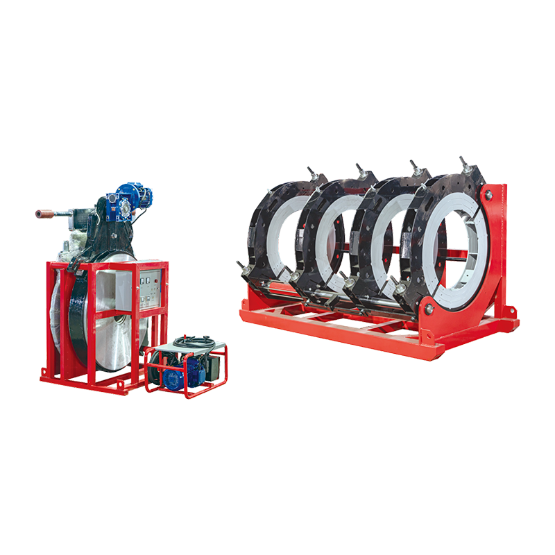
Hydraulic butt fusion welding machines extend the practical range upward to DN 630 mm and beyond, using hydraulic cylinders to apply and hold the precise fusion pressure specified in the welding procedure. Most modern hydraulic units include a pressure gauge and timer, but the operator still controls the sequence manually. These machines are the workhorse of gas distribution and water main installation projects globally.
CNC-controlled butt fusion welding machines automate the entire welding sequence — from surface facing verification through heating, changeover, fusion pressure ramp-up, and cooling. The machine logs all process data against a weld serial number, creating audit trails suitable for ISO 12176-4 compliance. These machines are the standard choice for critical infrastructure: offshore pipeline fabrication, gas transmission mains, and chemical plant piping where every weld must be traceable and the cost of a failed joint is extremely high.
Jointing Methods That Complement Butt Fusion
Even on projects dominated by butt joint configurations — where butt fusion welding machines handle the straight pipe runs — other joint types and welding processes appear at transition points:
- Electrofusion welding is used where pipe cannot rotate or where a butt fusion welding machine cannot access the joint location — in trenches with limited working space, close to walls, or when connecting to existing live mains
- Flanged connections transition between thermoplastic pipe and metal valves or equipment — not a fusion joint at all, but a mechanical interface
- Socket fusion is a form of overlap joint welding for small-diameter piping in building services — pipe and fitting are heated separately and pushed together, creating a joint that resembles a lap joint geometry
- IR butt fusion uses infrared heating instead of direct contact heater plates, eliminating contamination risk from degraded PTFE coating on traditional heater plates and speeding up changeover time to under 3 seconds on compatible machine models
Joint Preparation: The Step That Determines Weld Quality Before the Machine Starts
No butt fusion welding machine — regardless of how advanced its controls are — can compensate for poor joint preparation. The facing (trimming) step is critical: both pipe ends must be machined flat, parallel, and perpendicular to the pipe axis, with the facing cutter leaving a surface finish smooth enough to allow full contact across the mating area. A facing gap of more than 0.3 mm for pipes up to DN 400 mm (per DVS 2207-1) is grounds for rejection and re-facing before proceeding.
The facing cutter integrated into the butt fusion welding machine is a precision tool, but it wears. Dull facing blades produce torn rather than shaved surfaces, with visible tool marks and fiber pullout in the material. Regular blade replacement — typically every 50 to 100 facing operations depending on pipe material and diameter — is a maintenance task that project supervisors frequently overlook until weld quality problems appear.
After facing, pipe ends must not be touched with bare hands — skin oils transfer directly to the fusion surface and create contamination pockets that prevent molecular bonding. Lint-free gloves and a clean, dry workspace are baseline requirements, but they matter especially for the butt joint because the entire fusion area depends on two flat surfaces making uniform thermal and mechanical contact.
Ambient Conditions That Affect Butt Joint Fusion Outcomes
Wind, rain, and cold temperatures directly influence the thermal balance at the heater plate and the rate of heat penetration into the pipe wall. Most butt fusion welding machine manufacturers and welding procedure standards require that:
- Ambient temperature during welding be at least 5°C, with special cold-weather procedures for lower temperatures that extend heating time
- Wind shielding (a tent or windbreak) be used whenever wind speed exceeds 3 m/s to prevent uneven cooling of the heater plate and melt bead
- Pipe ends be dried and brought to ambient temperature before welding if they have been stored in cold conditions — fusion of a cold pipe end to a heated plate produces a surface melt that doesn't penetrate to the required depth
- Direct sunlight on the heater plate surface be avoided, as UV and uneven solar heating can cause surface temperature gradients that exceed ±5°C tolerance
Weld Bead Inspection: Reading the Butt Joint After Fusion
One of the practical advantages of the butt joint produced by a butt fusion welding machine is that the fusion bead (the rolled-over flash at the weld) is visible from the outside and provides real-time quality feedback without destructive testing. A properly formed bead should be:
- Symmetrical on both sides of the weld centerline — asymmetry indicates unequal heating or misaligned pipe ends
- Continuous around the full circumference — gaps or interrupted bead sections indicate insufficient heating time or contamination
- Within the bead height range specified for the pipe diameter and SDR — too small means under-fusion, too large suggests excessive heating or pressure
- Free of a visible groove or valley at the bead root (the line between bead and pipe surface) — a sharp groove indicates cold fusion at the interface
DVS 2202-1 and EN 12814-3 provide quantitative bead geometry acceptance criteria for HDPE and PP butt welds. Many quality programs also require periodic destructive testing — bend tests, tensile tests, and impact tests on production weld samples — to verify that the actual bond strength meets specification regardless of bead appearance.
For critical pipelines, phased array ultrasonic testing (PAUT) has become viable for HDPE butt welds in the past decade, detecting internal voids, cold fusion zones, and contamination inclusions that bead inspection cannot reveal. PAUT does not replace bead inspection but adds a non-destructive subsurface check that is increasingly specified on gas transmission and offshore pipeline projects.
Standards and Certifications That Govern Butt Fusion Welding
The butt joint in thermoplastic pipe systems is one of the most thoroughly standardized welded connections in any industry. The ecosystem of relevant standards covers equipment, procedures, operator qualification, and inspection:
| Standard | Scope | Region |
|---|---|---|
| ISO 21307 | Butt fusion welding procedures for HDPE pipes and fittings | International |
| ASTM F2620 | Heat fusion joining of HDPE pipe and fittings | North America |
| DVS 2207-1 | Welding of thermoplastics — butt welding of pipes, pipe components, and sheets made of PE | Germany / EU |
| ISO 12176-1 | Equipment for butt fusion welding of thermoplastics — requirements | International |
| ISO 12176-4 | Data logging requirements for butt fusion welding machines | International |
| EN 13067 | Plastics welding personnel qualification — thermoplastic welded assemblies | EU |
Operator qualification under EN 13067 or equivalent national standards requires both theoretical knowledge and a practical welding test witnessed by an approved examination body. Certified welders must demonstrate knowledge of all five basic joint types and be assessed specifically on butt fusion — including parameter setting, machine operation, bead assessment, and troubleshooting of common defects. Recertification is typically required every two years, with evidence of recent welding activity needed to maintain active certification status.
Common Defects in Butt Fusion Joints and How to Prevent Them
Understanding defect mechanisms in the butt joint is essential for anyone specifying or operating butt fusion welding machines. The most frequently documented failure modes are:
Cold Fusion
Cold fusion occurs when the mating surfaces are joined before reaching full melt temperature, or when changeover time is too long and the surface temperature drops below the melt threshold. The joint appears visually acceptable — the bead forms — but the actual molecular interdiffusion at the interface is insufficient. The weld passes visual inspection but fails under pressure or bend testing. Prevention: strict adherence to heating times, calibrated heater plate temperature, and tight changeover time control.
Contamination
Dirt, moisture, oil, or degraded PTFE coating from the heater plate transferring to the melt surface creates inclusions that bond poorly. Contamination is a leading cause of long-term creep failure in HDPE water pipe butt welds. Prevention: regular heater plate inspection and PTFE replacement, clean job sites, and handling protocols that prevent contact between bare hands or tools and the faced pipe ends.
Misalignment
Angular or lateral misalignment introduces bending stress at the weld zone. Even a 1° angular offset in a DN 400 HDPE pipe translates into a stress concentration that reduces fatigue life significantly under cyclic pressure loading. Prevention: proper pipe support, quality clamping fixtures on the butt fusion welding machine, and verification of alignment before and after facing.
Degradation at the Weld Interface
Overheating — heater plate temperature too high or heating time too long — causes thermal degradation of the polyethylene at the melt surface. Degraded material has lower molecular weight, reduced elongation at break, and increased susceptibility to oxidative attack. The weld may appear visually correct but will fail prematurely in service. Prevention: verified, calibrated heater plate temperature before each shift; no "banking up" of heat in thick-wall pipe by increasing temperature to shorten heating time.
Frequently Asked Questions
Which of the 5 joint types is strongest in fusion welding?
The butt joint consistently achieves the highest strength when full-penetration fusion is achieved, because the weld path runs continuously through the full cross-section without eccentricity or angular load path deviation. In HDPE thermoplastic pipe, correctly made butt fusion joints reach 95% or more of base material tensile strength.
Can a butt fusion welding machine weld all 5 joint types?
No. Butt fusion welding machines are designed specifically for butt joints on pipe ends and flat plate edges. T-joints, corner joints, lap joints, and edge joints require different equipment — extrusion welding guns, hot gas torches, or specialized jigs — or are addressed at the fitting/design stage rather than the field welding stage.
What diameter range do butt fusion welding machines typically cover?
Commercial butt fusion welding machines are available for pipe diameters from approximately DN 20 mm at the small end (socket fusion typically takes over below this) up to DN 1600 mm and in some configurations DN 2000 mm and beyond for large infrastructure projects. Each machine frame covers a defined diameter range, and reducer inserts or jaw sets allow one machine to handle multiple diameters within its rated range.
Is a lap joint ever used in pipe fusion welding?
In standard thermoplastic pipe networks, no — the lap joint is not a recognized joint type for pressure piping. It appears in HDPE geomembrane sheet welding for containment applications using wedge welders, and in socket fusion (which resembles a lap geometry), but not in the pipeline configurations where butt fusion welding machines are deployed.
How long does a butt fusion weld take to cool before the joint can be stressed?
Cooling time under fusion pressure varies with pipe wall thickness. For HDPE pipe, a common rule is a minimum of 10 minutes per millimeter of wall thickness at ambient temperatures above 10°C — meaning a 20 mm wall pipe requires at least 200 minutes of cooling before the joint can be released from the butt fusion welding machine and handled. Shorter cooling times are a common cause of cold-drawn welds that fail prematurely.