 English
 中文简体
中文简体 русский
 عربى
عربى

Content
- 1 What Is a Butt Weld Pipe and Why It Matters in Industrial Piping
- 2 The Core Welding Processes Used for Butt Weld Pipe Joints
- 3 Butt Weld Pipe Fittings: Standards, Dimensions, and Material Grades
- 4 How Butt Fusion Welding Machines Work: A Step-by-Step Overview
- 5 Butt Weld Pipe vs. Socket Weld vs. Flanged: When Each Connection Type Wins
- 6 Weld Joint Preparation: Bevels, Fit-Up, and Preheat Requirements
- 7 Non-Destructive Examination of Butt Weld Pipe Joints
- 8 Common Defects in Butt Weld Pipe and How to Prevent Them
- 9 Selecting the Right Butt Fusion Welding Machine for HDPE and PE Pipe Projects
- 10 Applications Where Butt Weld Pipe Is the Mandated Choice
- 11 Cost Considerations: Butt Weld Pipe vs. Alternative Joining Methods
What Is a Butt Weld Pipe and Why It Matters in Industrial Piping
A butt weld pipe is a pipe joined end-to-end by welding the abutting surfaces together, creating a continuous, flush connection with no overlapping material. The result is a joint that matches the pipe's own wall thickness, maintains full bore flow, and withstands the same pressure ratings as the parent pipe itself. In short: a correctly executed butt weld is mechanically equivalent to an unjointed length of pipe.
This method is the dominant joining technique across oil and gas transmission lines, chemical process plants, power generation facilities, water treatment infrastructure, and HVAC distribution networks. Engineers specify it wherever the priority is long service life, leak-free integrity, and minimal turbulence at the joint — which covers the vast majority of high-pressure, high-temperature, and corrosive-service applications.
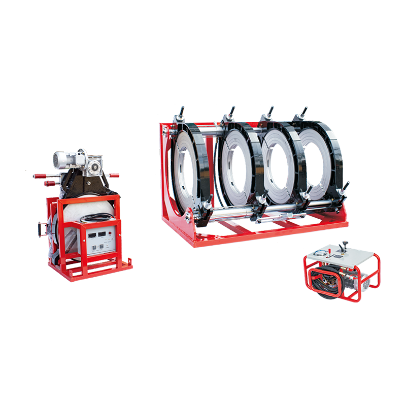
The term covers both metallic pipe (carbon steel, stainless steel, alloy steel, duplex) and thermoplastic pipe (HDPE, PP-R, PVDF, PE-RT), though the execution differs significantly between the two material families. Metal pipe relies on fusion arc processes and filler metals; thermoplastic pipe relies on heat and pressure applied by Butt Fusion Welding Machines, which melt mating surfaces and press them together without any filler material whatsoever.
The Core Welding Processes Used for Butt Weld Pipe Joints
Several distinct welding processes are used depending on material type, pipe diameter, wall thickness, and service environment. Understanding which process applies where is essential before specifying any piping system.
Shielded Metal Arc Welding (SMAW)
Also called stick welding, SMAW is the oldest and most field-portable process. It handles carbon steel and low-alloy pipe from small bore up to large diameter and performs well in outdoor, on-site, and overhead positions. Deposition rates are relatively low — typically 1.5–3.0 kg/hr — but setup costs are minimal and the equipment is rugged. SMAW remains standard for pipeline repair and tie-in welds where portability outweighs throughput.
Gas Tungsten Arc Welding (GTAW / TIG)
TIG welding produces the cleanest root passes on stainless steel, duplex, and high-alloy pipe. The process uses a non-consumable tungsten electrode and an inert gas shield (argon or helium), allowing precise heat control on thin-wall or small-diameter pipe. It is the mandatory process for pharmaceutical-grade and food-grade piping, where root bead smoothness directly affects cleanability. Deposition rates are lower than SMAW — often 0.5–1.5 kg/hr — but the metallurgical quality justifies the time.
Submerged Arc Welding (SAW)
SAW operates under a blanket of granular flux, which protects the arc and weld pool from atmospheric contamination. It is exclusively a shop or spool fabrication process — not usable in field positions — but achieves deposition rates of 10–40 kg/hr on heavy-wall large-diameter pipe. Refinery piping spools and structural headers are typical applications. The consistently high heat input requires careful preheat and post-weld heat treatment (PWHT) scheduling to control hardness in the heat-affected zone.
Butt Fusion Welding for Thermoplastic Pipe
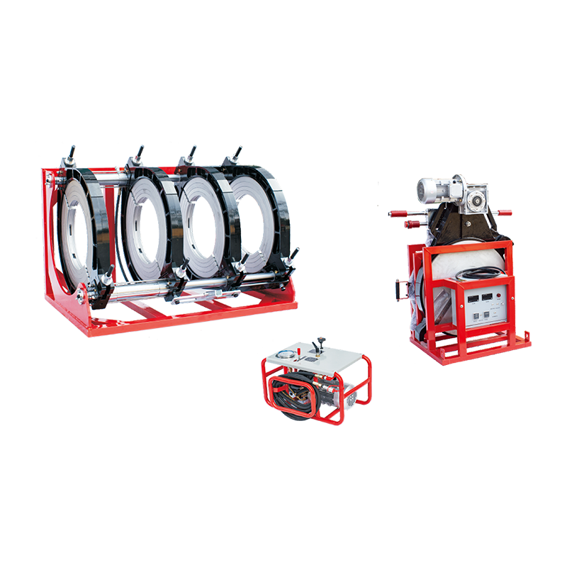
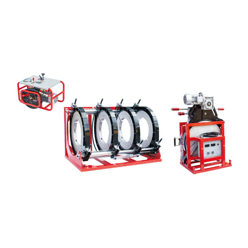
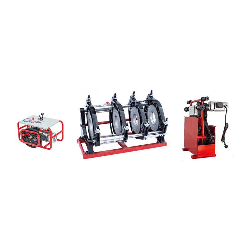
For polyethylene and polypropylene pipe, Butt Fusion Welding Machines replace all arc-based processes. The machine clamps both pipe ends, trims the faces flat with a rotary facing tool, then presses them against a heated plate at a precisely controlled temperature — typically 200–220 °C for HDPE — until a defined melt bead forms. The plate is removed and the two softened faces are pressed together under controlled force for a cooling period. The resulting joint is homogeneous: same material, same density, same chemical resistance as the pipe wall itself.
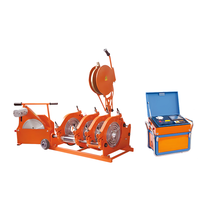
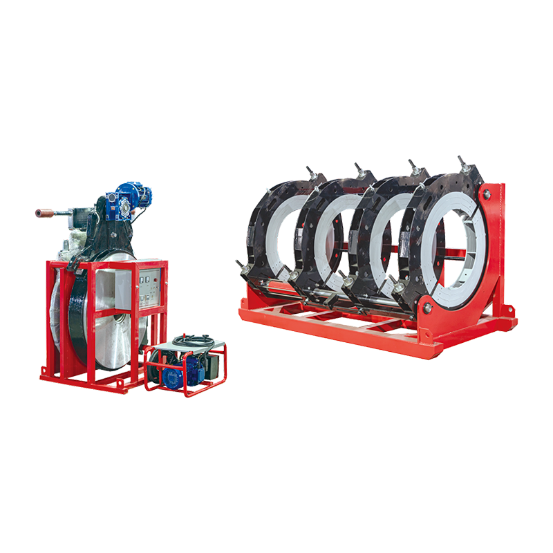
Modern butt fusion welding machines — from manual hydraulic units for DN63–DN315 pipe up to CNC-controlled hydraulic machines handling DN1200 and beyond — record all welding parameters (temperature, pressure, time, ambient conditions) digitally and export traceable weld logs per ISO 12176-4 and DVS 2202. This documentation trail is mandatory for gas distribution networks and potable water mains in most jurisdictions.

Butt Weld Pipe Fittings: Standards, Dimensions, and Material Grades
Butt weld pipe fittings — elbows, tees, reducers, caps, stub ends — are manufactured to specific dimensional standards that ensure interchangeability and weldability across different manufacturers' pipe. The dominant standards globally are:
- ASME B16.9 — Factory-made wrought buttwelding fittings, covering dimensions, tolerances, and pressure ratings for NPS ½ through NPS 48 in all common material grades.
- ASME B16.28 — Short-radius elbows and returns for space-constrained installations.
- MSS SP-75 — High-test wrought buttwelding fittings for pipeline-grade materials (WPHY-52, WPHY-60, WPHY-65, WPHY-70).
- EN 10253 — European standard covering seamless and welded butt weld fittings in carbon and austenitic stainless steel.
- ISO 4427 / EN 12201 — Polyethylene pressure pipe systems, specifying SDR ratios, OD tolerances, and fusion joint requirements for HDPE butt weld pipe.
Wall thickness schedules — SCH 10, SCH 40, SCH 80, SCH 160, XXH — determine the pressure capability of the butt weld pipe assembly. Selecting a lighter schedule to reduce material cost while maintaining the same nominal pipe size lowers the system's pressure rating proportionally; a DN100 SCH 40 carbon steel pipe (wall = 6.02 mm) is rated at approximately 100 bar at ambient temperature, while the same DN100 SCH 80 (wall = 8.56 mm) reaches roughly 160 bar. The fitting must match the pipe schedule, or a transition weld procedure is required.
| Pipe Size (NPS) | SCH 40 Wall (mm) | SCH 80 Wall (mm) | SCH 160 Wall (mm) | Typical Application |
|---|---|---|---|---|
| 1" | 3.38 | 4.55 | 6.35 | Instrument leads, hydraulic lines |
| 2" | 3.91 | 5.54 | 8.71 | Process lines, cooling water |
| 4" | 6.02 | 8.56 | 12.70 | Refinery headers, steam mains |
| 8" | 8.18 | 12.70 | 21.44 | High-pressure gas transmission |
| 12" | 9.53 | 14.27 | 25.40 | Pipeline trunklines, large headers |
How Butt Fusion Welding Machines Work: A Step-by-Step Overview
For thermoplastic pipe installers and procurement engineers unfamiliar with the process, the following describes how butt fusion welding machines operate through each phase. Deviating from any step — skipping a bead height check, rushing the changeover, or under-cooling the joint — reliably produces a substandard weld.
- Clamping and alignment. Both pipe ends are inserted into the machine's clamping jaws. Hydraulic or manual jaw alignment ensures the pipe axes are concentric within ±0.5 mm for pipe up to DN315, tighter for larger diameters. Misalignment at this stage creates an angular weld plane that concentrates stress under pressure cycling.
- Facing. A rotary facing tool trims both pipe ends simultaneously, removing surface contamination and creating flat, parallel mating faces. The facing tool is removed, and the gap between faces must be ≤0.3 mm for pipe up to DN180 and ≤0.5 mm for larger pipe (per DVS 2207-1). Any visible gap beyond these limits requires re-facing.
- Drag pressure measurement. With the heating plate absent, the machine applies force to bring the two pipe ends into light contact, measuring the hydraulic pressure required to move the carriage at a slow, steady speed. This drag pressure value is added to all subsequent welding pressures to compensate for friction in the machine's own hydraulic circuit.
- Heating plate insertion and bead formation. The heating plate — set to the material-specific fusion temperature, typically 210 °C ± 10 °C for PE100 — is inserted between the pipe ends. The machine presses both ends against the plate at bead-up pressure (a higher pressure) until a symmetrical circumferential melt bead of specified height has formed. For DN110 SDR11 PE100 pipe, the minimum bead height is approximately 1.5 mm per side; for DN315, it rises to about 3.0 mm per side.
- Heat soak (dwell). Pressure is reduced to near zero (heat soak pressure), and the pipe ends remain in contact with the plate for a calculated dwell time. This ensures the melt depth penetrates sufficiently into the pipe wall. For a DN200 SDR11 pipe, the dwell time is typically 60–70 seconds at standard conditions.
- Plate removal and join. The machine retracts both pipe ends simultaneously, and the operator removes the heating plate within a defined switchover time — typically 3–6 seconds depending on pipe size. Exceeding the maximum switchover time allows the melt surfaces to cool below fusion temperature and produces a cold weld. The machine then drives the pipe ends together at fusion pressure, forming the final joint bead.
- Cooling under pressure. The joint is held at fusion pressure for the full cooling time — calculated as approximately 10 minutes per 10 mm of wall thickness under standard conditions, though ambient temperature adjustments apply. Releasing pressure early while the weld is still molten at the core creates internal voids. The joint must not be moved, bent, or subjected to any axial load during cooling.
CNC-controlled butt fusion welding machines automate steps 3 through 7 entirely, with the machine calculating drag pressure, controlling plate temperature to ±2 °C, and timing each phase independently. They also reject non-conforming parameters in real time — if plate temperature drops below tolerance during dwell, the machine aborts and logs the event. For gas distribution contractors operating under EN 12007 or ASME B31.8, this level of documentation is not optional; it is the means by which weld traceability is established for the life of the pipeline.

Butt Weld Pipe vs. Socket Weld vs. Flanged: When Each Connection Type Wins
Piping engineers routinely choose between butt weld, socket weld, and flanged connections. Each has a domain where it is clearly superior; treating them as interchangeable leads to cost overruns or premature joint failures.
| Connection Type | Typical Pipe Size Range | Pressure Capability | Key Advantage | Key Limitation |
|---|---|---|---|---|
| Butt Weld | All sizes (NPS ½ and up) | Full pipe rating | No crevices, full bore, permanent | Requires skilled welder, RT/UT inspection |
| Socket Weld | NPS ½ – NPS 2 (NPS 3 max) | High (Class 3000/6000) | Easier alignment, lower welder skill | Crevice at root, not permitted in cyclic or corrosive service |
| Flanged | All sizes | Depends on flange class | Demountable — equipment connections, valves | Leak path at gasket, higher installed cost |
| Threaded | NPS ¼ – NPS 4 | Low-to-medium (Class 2000/3000) | No welding required, fast assembly | Notch stress, not for vibrating or cyclic service |
The single biggest driver toward butt weld is the absence of crevices. Socket welds trap a small annular gap between the pipe OD and the socket bore. In chloride-bearing, acidic, or elevated-temperature service, that crevice becomes a corrosion initiation site. ASME B31.3 Process Piping explicitly restricts or prohibits socket welds in cyclically loaded systems, in lethal fluid service, and in applications where crevice corrosion is a documented risk. Butt weld pipe eliminates the crevice entirely — the weld face is flush with the pipe bore when properly executed.
For thermoplastic systems, the equivalent comparison is between butt fusion (the default for pressure pipe), electrofusion couplings, and solvent cement joints. Butt fusion, achieved with dedicated Butt Fusion Welding Machines, is preferred for straight runs of DN63 and above because it requires no fittings, adds no external diameter at the joint, and produces the lowest installed cost per meter at scale. Electrofusion is preferred at tie-ins, in confined spaces where the fusion machine cannot straddle the fitting, and for branching connections where a saddle fitting is needed.
Weld Joint Preparation: Bevels, Fit-Up, and Preheat Requirements
Joint preparation is where butt weld pipe quality is largely determined — before the arc or heat plate is even applied. Incorrect bevel angle, poor fit-up, or inadequate preheat produces defects that no amount of welder skill can overcome once the joint is made.
Bevel Geometry for Metal Pipe
The standard single-V bevel for pipe wall thicknesses up to approximately 19 mm consists of a 37.5° bevel angle per side (forming a 75° included angle), a root face of 1.6–3.2 mm, and a root opening of 1.6–4.8 mm depending on process and pipe diameter. These dimensions come from ASME Section IX and AWS D10.11 and are the baseline from which procedure qualification testing is conducted.
For walls above 19 mm, compound bevels (J-groove, U-groove, or double-V) reduce the total weld volume significantly — a double-V uses approximately 40% less filler metal than a single-V on the same wall thickness — which directly reduces welding time, distortion, and residual stress. Heavy-wall headers and vessel nozzle attachments almost always use compound or narrow-groove preparations.
Hi-lo (radial misalignment between pipe ends) must not exceed 1.6 mm for most ASME B31.3 applications, or 10% of the thinner member's wall, whichever is less. Hi-lo concentrates bending stress at the joint root and is one of the top causes of early fatigue cracking in vibrating systems.
Preheat Requirements
Preheat slows the cooling rate in the heat-affected zone (HAZ), reducing the risk of hydrogen-induced cracking (HIC) — the dominant failure mode in carbon and low-alloy steel pipe welds. Preheat requirements are driven by carbon equivalent (CE), base metal thickness, and ambient conditions:
- ASTM A53 Gr.B / A106 Gr.B carbon steel, wall ≤25 mm: no preheat required above 10 °C ambient (per ASME B31.3 Table 330.1.1).
- Same material, wall 25–50 mm: minimum 79 °C preheat.
- Chrome-moly alloy pipe (P91, P22): minimum 200–250 °C preheat and mandatory PWHT, typically at 730–760 °C for 1 hour per 25 mm of wall.
- Ambient temperature below 0 °C: increase preheat by 55 °C for any material group.
Preheat must be measured at least 75 mm from the weld center using calibrated contact pyrometers or temperature-indicating crayons at a minimum of four equally spaced points around the circumference. Infrared guns read surface temperature, not through-wall temperature, and underestimate preheat sufficiency on thick-wall pipe.

Non-Destructive Examination of Butt Weld Pipe Joints
Inspection requirements for butt weld pipe are defined by the governing code, the fluid service classification, and the owner's specification. The choice of NDE method directly affects what defect types can be detected and at what defect size.
Radiographic Testing (RT)
RT — using X-ray or gamma ray sources — produces a two-dimensional projected image of the weld. It is highly effective at detecting volumetric defects: porosity, slag inclusions, incomplete fusion in the root, and undercut. It is less reliable at detecting planar defects (cracks, lack of sidewall fusion) oriented parallel to the radiation beam. ASME B31.3 requires 100% RT for Category M (lethal) fluid service and allows 5% spot RT for Normal fluid service. The practical sensitivity limit for most pipeline RT is a crack width of approximately 2% of the wall thickness.
Ultrasonic Testing (UT) and PAUT
Phased Array Ultrasonic Testing (PAUT) has largely displaced conventional single-probe UT for large-diameter or heavy-wall butt weld pipe inspection. PAUT electronically steers and focuses an array of transducer elements, producing a full cross-sectional scan of the weld volume with digital imaging. It detects planar defects that RT misses, provides accurate sizing data for fitness-for-service assessments, and generates auditable digital records. Sensitivity for PAUT on calibrated reference notches can reach 1.0 mm in height at the half-metal depth in typical pipeline applications. For subsea pipeline welds, PAUT with automated scanning systems (AUMT) is now the default examination method on most offshore projects.
Visual and Bead Geometry Inspection for Fusion Welds
For thermoplastic butt weld pipe joined with Butt Fusion Welding Machines, the primary post-weld inspection is visual bead geometry assessment per DVS 2202-1 or ISO 13953. The inspector measures bead height, bead width, and bead symmetry (inner and outer bead must be approximately equal in height) with a bead gauge. A double bead that is excessively asymmetric — one side materially taller than the other — indicates uneven heating, improper plate temperature, or a facing problem. Bead under-roll (bead height below minimum) often indicates excessive switchover time or plate temperature too low. Both conditions warrant destructive testing of a sample joint by tensile or peeling tear test before the weld is accepted.
The butt fusion weld log generated by the welding machine — recording welding pressure, plate temperature profile, switchover time, cooling time, ambient temperature, machine serial number, and operator ID — is the primary quality record for thermoplastic piping systems. Retaining these logs per the project specification (typically minimum 10 years, often asset life) is the difference between a system that can be confidently re-rated or extended and one that cannot.
Common Defects in Butt Weld Pipe and How to Prevent Them
Understanding the defect mechanisms in butt weld pipe joints allows project teams to write more effective welding procedure specifications, inspection hold points, and corrective action protocols. Most defects are preventable with disciplined procedure compliance; very few are truly random.
Porosity
Porosity in metal pipe welds results from gas entrapment in the solidifying weld pool — most commonly hydrogen from moisture in flux or electrode coatings, nitrogen from shielding gas loss, or carbon dioxide released from the parent metal. Preventing porosity requires dry, properly stored low-hydrogen electrodes (stored at 120–150 °C and used within 4 hours of removal from the oven for E7018), adequate shielding gas coverage, and removal of surface moisture or ice before welding. In GTAW root passes, back-purging the pipe bore with argon at a flow rate of 5–15 L/min is mandatory for austenitic stainless and nickel alloys.
Incomplete Root Penetration
A root that fails to fuse through the full joint thickness leaves an unfused land acting as a notch at the bore. This is particularly damaging in cyclic service because the notch concentrates tensile stress at the inner diameter — exactly where the highest stress amplitude occurs in pressure pulsation. Root penetration defects are prevented by correct root gap setting (per the WPS), not reducing amperage below the qualified range to control heat input, and using a root pass technique suited to the joint position (typically a keyhole technique for 6G pipe position GTAW).
Cold Welds in Thermoplastic Butt Fusion
A cold weld in a fusion-welded thermoplastic pipe joint occurs when the melt surfaces cool below the crystallization temperature before being pressed together. Typical causes: switchover time exceeded (most common), heating plate temperature too low, or ambient wind stripping heat from the exposed melt faces. Cold welds appear visually similar to sound welds — the double bead is still present — but fail at a fraction of the design pressure. Detection requires destructive testing (tensile or peeling test) or hydrostatic testing; visual inspection alone cannot reliably identify a cold weld. Prevention is entirely procedural: strict adherence to the welding datasheet for the specific pipe material, diameter, and SDR, and shielding the machine from wind during the joining phase.
Hydrogen-Induced Cracking (HIC)
HIC in carbon and low-alloy steel pipe manifests as underbead cracking in the HAZ, typically found 24–72 hours after welding as residual stress drives delayed diffusion of hydrogen to susceptible microstructural sites. It is the most insidious metal pipe defect because it develops after the weld has passed immediate NDE inspection. Prevention requires low-hydrogen electrodes (diffusible hydrogen ≤4 mL/100 g deposited metal for H4 classification), adequate preheat and interpass temperature, and sometimes post-heat (holding at 200–300 °C immediately after welding to allow hydrogen to diffuse out before the joint cools fully). High-restraint joints and thick-wall high-CE pipe are the highest-risk scenarios.

Selecting the Right Butt Fusion Welding Machine for HDPE and PE Pipe Projects
Contractors sourcing Butt Fusion Welding Machines for thermoplastic pipeline projects face a range of configurations, from basic manual hydraulic units to fully automated CNC systems with integrated data logging. The right choice is determined by pipe diameter range, project volume, documentation requirements, and site conditions.
Manual Hydraulic Machines (DN63–DN315)
Entry-level butt fusion welding machines in this class use a manually operated hydraulic pump to generate clamping and fusion pressure, with a separate temperature-controlled heating plate. The operator monitors bead formation visually and controls timing manually using a stopwatch and a pressure gauge. These machines cost between USD 3,000 and USD 12,000 depending on size range and brand, making them accessible for small contractors. Their limitation is operator dependency: pressure ramp rates, switchover time, and cooling duration are all human-controlled and therefore variable. For water utility work and low-risk non-pressure applications, this variability is acceptable. For gas distribution or high-pressure slurry lines, it is not.
Semi-Automatic Hydraulic Machines (DN110–DN630)
Semi-automatic butt fusion welding machines automate the pressure phases via a programmable controller but still require the operator to insert and remove the heating plate manually. The controller calculates drag pressure, sequences bead-up and heat soak phases, and alarms on out-of-tolerance conditions. These machines typically include a printer or USB/Bluetooth data export for weld log generation. They represent the current standard for gas distribution contractors across Europe, where WRC/DVGW and IGEM/UP/2 approval requires traceable documentation of every production weld. Price range: USD 25,000–80,000 for DN315–DN630 capacity.
Fully Automatic CNC Machines (DN200–DN1200+)
Top-tier butt fusion welding machines automate the entire welding cycle — the machine moves the heating plate in and out, calculates all welding parameters from pipe geometry and material inputs, and rejects the weld automatically if any parameter falls outside the procedure window. Some current models integrate RFID pipe-tracing (scanning a pipe tag to auto-populate the welding datasheet), real-time cloud upload of weld records, and GPS coordinates for each weld position. For large water transmission main projects or cross-country HDPE gas pipelines, the reduction in operator error and the completeness of the audit trail justify the capital cost of USD 100,000–250,000 per machine.
Key specifications to confirm before purchasing or renting any butt fusion welding machine include: pipe diameter and SDR range (jaw inserts often cover 2–3 SDR values per size range), heating plate temperature uniformity (±5 °C across the face is the standard requirement), maximum hydraulic pressure output (must exceed the calculated fusion pressure for the largest pipe in the range plus safety margin), and data logging format (confirm compatibility with the project's quality management system before mobilization).
Applications Where Butt Weld Pipe Is the Mandated Choice
Certain industries and codes do not leave joining method selection to the engineer's preference; butt weld is mandated by the applicable standard or by decades of performance data that has eliminated alternatives from the specification.
- Subsea and offshore pipelines: All weld joints on flowlines, risers, and export pipelines are butt welds executed to DNV-ST-F101 or API 1104. The combination of external hydrostatic pressure, internal process pressure, and cathodic protection interaction rules out any non-welded connection. Girth welds on 12" SCH API 5L X65 pipe operating at 200 bar are qualified through full qualification test programmes including CTOD fracture toughness testing at −10 °C.
- Nuclear power plant piping: ASME Section III Class 1, 2, and 3 piping systems prohibit socket welds above NPS 2 and require volumetric examination (RT or UT) of all butt welds in Class 1 service. The combination of radiation environment, seismic loading, and lethal-if-released fluid inventories leaves no margin for joint types with crevices or stress concentrations.
- Natural gas distribution mains (PE pipe): Virtually every national gas distribution specification — IGE/UP/2 (UK), DVGW G472 (Germany), AS/NZS 4130 (Australia/NZ) — mandates butt fusion or electrofusion joining for medium-density and high-density polyethylene (MDPE/HDPE) gas pipe in the field. Compression fittings and push-fit joints are restricted to specific service connections and repair applications only.
- High-purity pharmaceutical and semiconductor process lines: Orbital TIG welding (an automated GTAW variant) producing mirror-smooth internal root beads is the standard for 316L stainless steel tubing in these applications. The butt weld with full penetration and no backing ring is required to prevent product contamination in dead-leg crevices. Welds are typically internally borescope inspected at a 100% inspection rate on critical loops.
- Power plant high-energy piping: Main steam, hot reheat, and feedwater piping operating above 100 bar and 400 °C in coal, gas, and nuclear plants is designed, fabricated, and inspected to ASME B31.1 Power Piping. All girth welds are butt welds, subject to 100% UT on P91 chrome-moly material and 20–100% RT on carbon steel depending on pipe size and service classification.
Cost Considerations: Butt Weld Pipe vs. Alternative Joining Methods
The installed cost of butt weld pipe is higher than socket weld or flanged pipe on a per-joint basis, but lifecycle cost comparisons consistently favor butt weld for permanent, high-cycle, or high-integrity service. The cost breakdown breaks down as follows:
Direct Installation Cost
A typical butt weld joint on 4" SCH 40 carbon steel pipe in a process plant spool fabrication shop involves bevel preparation, fit-up, tack welding, SMAW root pass, two or three fill/cap passes with FCAW, NDE (spot RT), and documentation. Total welder hours: approximately 2.0–3.5 hours per joint depending on position, accessibility, and welder qualification level. At a loaded labor rate of USD 75–120/hr in North America, the direct welding cost per joint is USD 150–420. Adding NDE (approximately USD 80–150 per RT shot for a 4" pipe) and supervision, a 4" butt weld joint in field piping costs roughly USD 300–600 installed.
A comparable 4" flanged joint — weld neck flanges, gasket, and bolts — costs USD 120–250 in materials alone, plus the same welding cost for the two flange-to-pipe welds, plus gasket replacement every major overhaul cycle. Over a 30-year plant life with three major turnarounds, the flanged joint lifecycle cost exceeds the butt weld joint by a significant margin on any line that does not require routine disassembly.
Cost of HDPE Butt Fusion Joints
For HDPE pipe using Butt Fusion Welding Machines, the economics are highly favorable compared to electrofusion couplings on straight runs. A DN315 SDR17 HDPE butt fusion joint using a semi-automatic machine takes approximately 45–60 minutes total cycle time including setup, facing, and cooling. Machine cost amortized over a 5,000-joint project — assuming a 5-year machine life and 1,000 joints per year — adds roughly USD 15–25 per joint. An equivalent DN315 electrofusion coupling costs USD 180–350 in material alone. On a 10 km water main project with 400 DN315 joints per kilometer (assuming 12 m pipe lengths), butt fusion saves approximately USD 60,000–130,000 in fitting costs per kilometer compared to electrofusion — before counting any labor differential.